Ops Amp

Thread Starter

forbi

Joined Sep 11, 2012
37
Ops Amp.jpg

Hi,
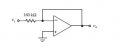
how do you do an analysis on this circuit to get the gain = 0?

this is like a voltage follower but with a resistor at the input terminal.

i know the input resistance is 160k ohm and output resistance is 0 ohm.
Op Amp 2.png

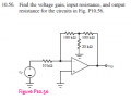
About this circuit. i tried to redraw the circuit as such,

cos there is a common ground between the input voltage, 20k resistor and Vo

----10k---100k---|--------100k-----|
|xxxxxxxxxxxxxxxx| xxxxxxxxxxxxxxxxx|
|xxxxxxxxxxxxxx | xxxxxxxxxxxxxxxxx|
Vi xxxxxxxxxxxxxx 20k xxxxxxxxxxxxxxx Vo
| xxxxxxxxxxxxxxx|xxxxxxxxxxxxxxxxx |
|-----------------------------------|

I did using superposition.
going around left side and right side.

Vi ( (20k//100k)/(110k + 20k//100k) ) = Vo (- (110k//20k)/(110k//20k + 100k))


but it doesn't give me the correct answer which is -70 gain
 
Last edited:

t_n_k

Joined Mar 6, 2009
5,455
If you consider the first circuit you'll hopefully recollect that the op-amp with feedback shown will have the output adjusting to make the -ve terminal potential equal the +ve terminal potential. Since +ve is tied to ground the -ve terminal will be at ground potential. So the output will also be at ground potential or 0V.
 

Thread Starter

forbi

Joined Sep 11, 2012
37
If you consider the first circuit you'll hopefully recollect that the op-amp with feedback shown will have the output adjusting to make the -ve terminal potential equal the +ve terminal potential. Since +ve is tied to ground the -ve terminal will be at ground potential. So the output will also be at ground potential or 0V.
So for the first diagram is actually an "unless" ops amp since it doesn't provide any amplification and even "blocks" the voltage
 
You are essentially providing 100% feedback!!

So no voltage gain out!!

A much simplier way is to think of it this way.

The gain equation for a an inverting amplifier is - rf/r1 x voltage in

Now in your case the rf is essentially equal to zero as you have no resistance and we will ignore the resistance of the wire!! So,

0/r1 x voltage in is equal to 0.

Tadaaaaaaaah!!!!


Also the other circuit is called a t junction! I'm sure there is analysis on the net somewhere for it!!
 

t_n_k

Joined Mar 6, 2009
5,455
For a clever shortcut one can make use of the star-delta transformation of the feedback network. The result is then quite obvious.
 

Thread Starter

forbi

Joined Sep 11, 2012
37
For a clever shortcut one can make use of the star-delta transformation of the feedback network. The result is then quite obvious.
. ops amp star delta.png

i did a star delta . what should i do with the 140kohm resistor? do i ignore them? if so the answer is correct with an inverting gain of
-700kohm/10kohm = -70

but why do i ignore the 140kΩ resistor ?
 
T n K, you surprise me. There may not be any voltage gain, but there certainly is current gain. It's a classic circuit to act as a virtual ground that needs a decent impedance to work against.
 

t06afre

Joined May 11, 2009
5,934
T n K, you surprise me. There may not be any voltage gain, but there certainly is current gain. It's a classic circuit to act as a virtual ground that needs a decent impedance to work against.
The inverting opamp configuration is sometimes refferd to as a curreent to voltage conveyr/converter. I have used this skin conductance measurements systems. Using the skin conductance it self as the input impedance in a inverting opamp configuration, and a 3 electrode system
 

t_n_k

Joined Mar 6, 2009
5,455
T n K, you surprise me. There may not be any voltage gain, but there certainly is current gain. It's a classic circuit to act as a virtual ground that needs a decent impedance to work against.
Thanks for the correction. Goes to show you can teach an old dog new tricks.
 

t_n_k

Joined Mar 6, 2009
5,455
. View attachment 46472

i did a star delta . what should i do with the 140kohm resistor? do i ignore them? if so the answer is correct with an inverting gain of
-700kohm/10kohm = -70

but why do i ignore the 140kΩ resistor ?
The 140k at the negative input is essentially connected between virtual ground and physical ground. It therefore has no potential difference across its terminals and therefore has no current. As such it can be ignored. The other 140k connects the output to ground, thereby behaving as a load on the output. For an ideal op-amp this will have nill effect on the gain.
 

Thread Starter

forbi

Joined Sep 11, 2012
37
Wow this is interesting , my prof keep doing "magic" by relating things like no current flow here or is connected to virtual ground and by eliminating this resistor first. By doing all his "magic" the whole complicated circuit seems very easy to analys .
How do my prof or anyone able to deduce such conclusion such as no current flow through some resistor or elimination?
This is so "magicial" !
 
Top