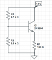
Operation point at rest of transistor

Thread Starter

AD633

Joined Jun 22, 2013
96
Hello,

I was trying to determine the operation point at rest (the values of Ic,Ib and Vce) for the transistor in the circuit.
I know that Vbe=0.7 V hfe=60

Could you please check if this is correct?

\( Vb=12V*(3.3*10^3 Ohm)/(2.7*10^3 +3.3 *10^3)
Vb=6.6 V \)

\( Ve=Vb-Vbe=6.6 V-0.7 V=5.9 V


Vce=Vc-Ve=12-5.9 V=6.1 V

Vcc=Vce2+Re*Ie

Vcc=Vce2+Re*Ic

12 V=6.1 V+100 Ohm*Ic

Ic=59mA

\)

Therefore \( Ic=Ie=59 mA\)

So i get \( Ib=983.33uA
Ic=59 mA
Vce=6.1 V \)

Is this right?

Thanks
 

Attachments

t_n_k

Joined Mar 6, 2009
5,455
You've neglected to take into account the voltage drop in the voltage divider bias network itself.

The base voltage will be less than 5.9V. The actual emitter and collector currents will be substantially less than 59mA.

Probably depends on the method you have been taught, but I would think this approach is not consistent with the typical "standard" method for BJT voltage divider bias analysis.
 

Thread Starter

AD633

Joined Jun 22, 2013
96
You've neglected to take into account the voltage drop in the voltage divider bias network itself.

The base voltage will be less than 5.9V. The actual emitter and collector currents will be substantially less than 59mA.

Probably depends on the method you have been taught, but I would think this approach is not consistent with the typical "standard" method for BJT voltage divider bias analysis.
Should i analyse the circuit as if it was a fixed bias montage with voltage divider biasing,despite the lack of a resistor in the colector?

Thanks
 
Last edited:

LvW

Joined Jun 13, 2013
2,037
Yes - t_n_k is right.
You must take into account that the current through R2 is larger than through R3 (because of the base current Ib).
Using the assumption Ie=Ic you arrive at a system of three equations for three unknown values:
V(base), Ic and a factor k=I(3.3k)/Ib.
(Thus, k tells you how much larger the current through R3 is if compared with Ib).
This can be easily solved.
And yes - as t_n_k has mentioned, the resulting current Ic will be considerably smaller than gcalculated by you.
 

Thread Starter

AD633

Joined Jun 22, 2013
96
Yes - t_n_k is right.
You must take into account that the current through R2 is larger than through R3 (because of the base current Ib).
Using the assumption Ie=Ic you arrive at a system of three equations for three unknown values:
V(base), Ic and a factor k=I(3.3k)/Ib.
(Thus, k tells you how much larger the current through R3 is if compared with Ib).
This can be easily solved.
And yes - as t_n_k has mentioned, the resulting current Ic will be considerably smaller than gcalculated by you.
So can i analyse the circuit as having fixed voltage divider biasing with emitter resistor,although that the resistor in the colector is missing?
 
Last edited:

LvW

Joined Jun 13, 2013
2,037
So can i analyse the circuit as having fixed voltage divider biasing with emitter resistor,although that the resistor in the colector is missing?
It is absolutely not important if there is a collector resistance or not.
The BJT can be seen as a current source - and it`s behaviour does not depend on a possible load of this current source.
 

WBahn

Joined Mar 31, 2012
33,201
I good sanity check for bias networks like this is to do the following:

1) Assume that the base current is zero and determine the current flowing in the bias network.

2) Analyze the circuit and determine the approximate base current.

3) Compare the base current to the current in the bias network. If it is not at least 50x smaller, or so, then you can't ignore it.

Another comparable way is to find your estimated base current and then see what the voltage drop across the bias network resistor would be just due to the base current. If that change in base voltage is significant for you, then you can't ignore the base current.

In this case, you have 59mA, which means a base current of about 1mA, which means a drop of 2.7V across the top resistor. So you can expect the base voltage to be lower than the zero-base-current case by about 3V, which is a 50% change in emitter voltage. That's significant.

Once again, it falls in the category of always asking if the answer makes sense. With experience and practice, you will develop a little bag of checks that you just automatically make, almost without thinking about it. But it does require that you consciously and deliberately do it until it becomes habit.
 

WBahn

Joined Mar 31, 2012
33,201
\( Vb=12V*(3.3*10^3 Ohm)/(2.7*10^3 +3.3 *10^3)\)
You are doing a much better job of tracking your units, so I'm just pointing out the line above to bring it to your attention.

You can use \Ohm in a tex block to get the Ω symbol.

Under the assumption of zero base current, your approach an analysis is correct. Now you just need to start asking if your assumptions make sense. The first part of that is always being aware of what your major assumptions are. It is a good practice to actually list them prior to using them in the analysis. That not only forces you to consider them, at least briefly, but also lets others understand where you are coming from, apply the same assumptions when checking your work, and testing whether or not the assumptions are valid.
 
Top