Open drain output LED control

Thread Starter

nick175

Joined Sep 27, 2010
5
Hi All,

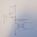
I've got a device which uses an open-drain output, this pulls to GND when a fault occurs.
Currently I have a photomos device on the output where the LED switches off when a fault is detected. This all works fine.

I would now like to add an additional LED which illuminates when a fault is detected, therefore when the open drain output pulls to ground.

My brain has turned into mush and I can't quite work out how to achieve this. Attached is the circuit I have so far resistor value is 3k9.
 

Attachments

ericgibbs

Joined Jan 29, 2010
18,766
hi nick,
Welcome to AAC,
Add the LED to the lower end of that resistor, , you may have to reduce the resistor value to suit the photomos and the LED,
Approx 5mA thru 10mA is enough to light an LED.
E
 

Thread Starter

nick175

Joined Sep 27, 2010
5
Hi Eric,
Would that work, as wouldnt the LED still be illuminated while everything is good. I.e. the open drain output is High-Z.
I only want the LED to illuminate when the unit detects a problem and the open-drain output pulls to ground.
 

bertus

Joined Apr 5, 2008
22,270
Hello,

I think that indeed the extra led will light when the drain is open.
On the open drain output there will be about 1.2 volts (IR led) when high-z situation is active.
You likely would need a comparator to monitor the voltage on the open drain output.
With a switchpoint of about 0.6 volts you would be fine.

Bertus
 

Thread Starter

nick175

Joined Sep 27, 2010
5
I may need to just build it up to confirm with myself.

Just under healthy conditions, the high-Z open drain isnt taking much, therefore the photomos LED is on, and wouldnt the extra LED be illuminated under this condition.

I understand the LED will illuminate under a fault condition when the open-drain pulls to ground. But I need the LED to be off when the open-drain is in high-Z state.
 

Thread Starter

nick175

Joined Sep 27, 2010
5
Thanks Eric, I will give that a go. Would be a nice simple solution if it works and cant see why it wouldnt.

I had tried thinking about using transistors etc to invert ad act as a switch, but currently cant figure a way, due to having the photomos there.
 
Top