Opamp output voltage calculation question

Thread Starter

S€b

Joined Apr 29, 2017
7
Hi there.

I'm planning on working with the TGS5141 carbon monoxide sensor (datasheet attached).

In the datasheet I read the following:
xxxx = sensor's sensitivity (slope) in numeric value as
determined by measuring the sensor's output in
300ppm of CO (Ex.1827=1.827nA/ppm)


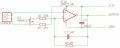
In this example, this particular sensor gave an output at 1.827nA per ppm measured at 300ppm which would then translate to 548.1nA (0.5481uA) at 300ppm. The opamp then amplifies this small current into an output voltage. I assume the 1M resistor in the diagram should be a low tolerance resistor (maybe trimpot), I guess this in combination with the sensor is maybe part of a voltage divider?

Is there any way to know the output voltage from the opamp at 300ppm (based on the known configuration and nA per ppm)
I guess this depends on the used opamp and that the conversion ratio for nA to V may be in the datasheet for the opamp, is that correct?

The circuit mentions the use of the AD708, I didn't find many suppliers for this one on Aliexpress and had a look at the LF356N (datasheet attached) which requires according to the datasheet a low input bias current of 30pA. As in this example we have 1.827nA per ppm, 30pA would be sufficient right? Or did I misunderstood the the function of input bias current?

I have serious trouble in figuring out the output voltage from the opamp at 300ppm. I looked at some online calculators but they all seem to ask for input voltage and the datasheet for this sensor only mentions a certain uA at 300ppm. Could anyone shine some light on this as I would like to understand how to this conversion is calculated.

All help is appreciated :)
 

Attachments

AnalogKid

Joined Aug 1, 2013
10,987
The output of the opamp circuit is directly related to the accuracy of the feedback resistor. An untrimmed 5% tolerance resistor means that the best-case output voltage accuracy will be +/-5%.

The circuit is called a transimpedance amplifier. The function equation is almost identical to Ohm's Law. In this case the amp is inverting, so the output voltage is:
V = -I x R

An input of -1 uA and a resistor of 1 M yields an output of +1 V.

30 pA is a low bias current, but not as low as other FET-input or CMOS opamps. Again, it depends on your error budget for the circuit.

ak
 
Last edited:

Thread Starter

S€b

Joined Apr 29, 2017
7
Wow thank you so much AK for helping me out. It had been puzzling me for days to the point I started to dream about it :-D

Which opamp would you recommend to get the best result (lowest error margin)?
 

Thread Starter

S€b

Joined Apr 29, 2017
7
Thank you both for educating me, always good to learn new things :)
If 1uA (1000nA) equals 1V (1000mV) and this particular sensor measures 1.827nA per ppm, 5mV would equal 5nA (almost 3ppm) right?
In that case I would like to have a lower offset (lowest possible).

Do you happen to know a very good opamp (I don't mind paying a little more for a good opamp)
Preferably with an offset of less then 1.8mV (1ppm), the lower the better :)
 

Thread Starter

S€b

Joined Apr 29, 2017
7
I just had a quick look at the AD708 and read in the datasheet "30 μV maximum offset voltage" I guess that is why they had it in the sensor diagram. I guess I will go for that one then :)
 
You might want to look here: https://sgx.cdistore.com/datasheets...n-of-Electronics-for-EC-Sensors-V3.pdf#Page=6 (opens to page 6)

They suggest this http://www.ti.com/lit/ds/symlink/opa2234.pdf one.

Note that they have the FET circuit.

If your new, don't forget bypass capacitors. These caps are usually around 0.1 uF and ceramic and are located close to the power supply pins. The manufacturer generally suggests values.

With I-V converters, input bias current (Ib)and offset voltage (Vos) are the real important parameters. They both change with temperature.
 

Thread Starter

S€b

Joined Apr 29, 2017
7
Thanks guys! Much appreciated! :)

Yeah, my knowledge is unfortunately limited.
I will make a circuit diagram that I will lay out here to ask if I did it correct.
Math is not my strongest point so I have to think hard about the temperature correction equation for both the sensor and opamp (temperature data from the BME280 will be available) but I guess I think about that after I have a working setup.
 
I'm not sure why you have C2 in the circuit. I don't see any bypass caps (power supply of op amp to ground close to the OP amp)

Depending on exactly what your trying to do. It's sometimes helpful to put a low value resistance in series with the output of the OP amp.

Is reverse polarity protection useful? It could be a reverse biased diode in parallel with the supply and a fuse in series with the power.
 

Thread Starter

S€b

Joined Apr 29, 2017
7
Thanks :)
I don't think I need a reverse polarity protection (at the moment). I also changed C2 into a bypass :)
The only thing I try to accomplish is a more accurate analog reading from my CO sensor.

Would R1 and R2 not influence the reading negatively (I'm no expert what so ever, so I'm only asking) :)
If a low value resistor on the output is of any help than I am more than happy to do that. Would that somehow reduce the voltage reading?

Uploaded a new version, not sure if this is correct.
 

Attachments

Audioguru

Joined Dec 20, 2007
11,248
Your other thread for this project (why two threads??) shows the datasheet for the CO sensor, a recommended circuit in the datasheet and your correct copy of that circuit. Now you added a Mosfet that is not biased correctly and it is completely wrong.
 
Check to see if the FET is wired correctly.

The manufacturer recommends 10nF for bypass.

The single channel version of the OP-amp has better Vos specs and can be nulled with the addition of a potentiometer. Usually this is a 10-20 turn trimmer. You can design the board with it, but you only have to populate it if you need it. Using a trimmer can affect other parameters, but as the datasheet suggests usually minimally, if at all.

In one I-V converter design I did, I wanted to use a D/A to null the amplifier, but my D/A would not output exactly 0 V. We only really cared about AC performance anyway. Without nulling, I only had ~ 40 pA of offset current and that was a tiny part of say 1-10 mA. I based the design on the OP41 http://www.analog.com/media/en/technical-documentation/data-sheets/OP41.pdf metal can package at the time. It allowed me to lift the input pin and place it on a Teflon standoff.

In your layout, you could implement a guard trace. See https://electronics.stackexchange.com/questions/24852/implementing-guard-trace-ring-in-pcb-design It would be at ground potential in your case.

Small resistors in series with the output like <100 ohms can isolate capacitance. If your A/D or whatever has a high input Z, e.g. 10 megohms, 100 ohms won't affect the reading to worry,
 
Top