Op Amp TLE2141

Thread Starter

Milenia

Joined Jul 23, 2013
5
Hi all.

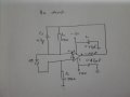
I am having problem when using Op Amp TLE2141 amplifier. The problem is my output signal voltage at pin 6 is 32mv. I give the voltage supply is 18v. I want to increase the voltage to volt at least 4v. Can someone give me suggestion regarding my problem :(
 

shteii01

Joined Feb 19, 2010
4,644
To review available info:
Top rail: 18 V
Bottom rail: ?
Output: 32 mV
Input: ?

Did you setup input resistor?
Did you setup feedback resistor?
 

Thread Starter

Milenia

Joined Jul 23, 2013
5
Top rail: +18V
Bottom rail:-18V
Output: 32mV

What do you mean for input? is it input at pin no 2 and 3? Here is my schematic diagram. Whenever I change the Vcc from +15V -15V, there is no respond. Still in milivolt.
 

Attachments

Last edited:

shteii01

Joined Feb 19, 2010
4,644
Top rail: +18V
Bottom rail:-18V
Output: 32mV

What do you mean for input? is it input at pin no 2 and 3? Here is my schematic diagram. Whenever I change the Vcc from +15V -15V, there is no respond. Still in milivolt.
That does not look like amplifier circuit. It got some filter elements, but that just my opinion on first glance, not a professional opinion.

What are you trying to accomplish?
I ask because this: "I want to increase the voltage to volt at least 4v." Does not make sense to me.
 

Thread Starter

Milenia

Joined Jul 23, 2013
5
@shteii01
I want to increase the output voltage at pin no 6 at least in volt. Supposed to be 4V. I expect that when I increase the Vcc, hopefully can increase the output voltage of TLE2141 at pin no 6 to 4V. But, it does not work.

@Dodgydave
Thank you for your suggestion. I will try. Can I increase the -ve supply of diode until 15v? or its value depends on my Vcc supply?
 

shteii01

Joined Feb 19, 2010
4,644
@shteii01
I want to increase the output voltage at pin no 6 at least in volt. Supposed to be 4V. I expect that when I increase the Vcc, hopefully can increase the output voltage of TLE2141 at pin no 6 to 4V. But, it does not work.

@Dodgydave
Thank you for your suggestion. I will try. Can I increase the -ve supply of diode until 15v? or its value depends on my Vcc supply?
With amplifier there are two ways to increase output:

1) Increase input.

2) Increase gain.

Example.
Input 1 volt. Gain is 2. Output will be 2 volt.
Increase Gain to 4.
Input 1 volt. New Gain is 4. New Output is 4 volt.

Supply provides the limits of output. Your supply is 15 volts. Your desired output is 4 volts. You are within the supply limits, therefore increasing supply does absolutely nothing for you.
 

Thread Starter

Milenia

Joined Jul 23, 2013
5
@shteii01

Thanks for your good explanation :). I have been try do like your suggestion. And I put led on TLE2141 at pin no 6. And the led's is on. However, when I put oscilloscope probe at pin no 6, it shows 32mv on the oscilloscope screen. Why does it happen? Because I have try measure the voltage at LED using multimeter and it shows 2.2V. Do you have any idea about that? I little bit confuse about this situation
 

shteii01

Joined Feb 19, 2010
4,644
@shteii01

Thanks for your good explanation :). I have been try do like your suggestion. And I put led on TLE2141 at pin no 6. And the led's is on. However, when I put oscilloscope probe at pin no 6, it shows 32mv on the oscilloscope screen. Why does it happen? Because I have try measure the voltage at LED using multimeter and it shows 2.2V. Do you have any idea about that? I little bit confuse about this situation
Not sure what is up with oscilloscope. I am ok in using oscilloscope, but I am not really a "superuser".

Is this the type of circuit you are trying to build: http://www.robotroom.com/ReversedLED.html

Are you trying to use a regular LED as a light or color detector?
 

Thread Starter

Milenia

Joined Jul 23, 2013
5
I used regular LED as indicator that shows to me that my photodiode received the signal. I agree with you that it supposed to be ok if using oscilloscope. Maybe i should try harder. Thanks for your help :)
 

shteii01

Joined Feb 19, 2010
4,644
I used regular LED as indicator that shows to me that my photodiode received the signal. I agree with you that it supposed to be ok if using oscilloscope. Maybe i should try harder. Thanks for your help :)
Ok. The photodiode has a different symbol. The light arrows point toward the diode. In your drawing the light arrows point away from diode, that is not symbol for photodiode, it is symbol for light emitting diode.

I have been sort of comparing your drawing to some other circuits. Do you need the R1 resistor? The one from non-inverting input to op-amp to the ground. The circuit that Dodgydave linked: http://www.linear.com/solutions/1200 seems to be the one you are trying to build. It does not have a resistor where you have R1.
 

DickCappels

Joined Aug 21, 2008
10,661
Dodgydave already told you how to modify your circuit to make it work (connect the diode anode to -15V instead of the + input).

R1 in series with the + input is a good idea to compensate for the offset generated across R2 by input leakage current. Without R1, the offset across R2 could be several volts (couple microamps x 1.5 Meg).
 
Top