
Hello everyone!
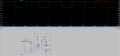
Disclaimer: I am quite inexperienced with analog electronics. I have tried to simulate a constant current source in LTspice, which is composed of an rail-to-rail input/output OP-amp (LT1218 powered with a 5V supply and the other power pin set to ground) and a power-mosfet (IRFZ44N), because it is meant to drive a current of approximately 1A. The non-inverting input of the OP-amp is connected to a voltage divider, which represents a potentiometer for setting the current. It is powered by a square-wave voltage source, which ranges from 0 to 5V with a duty cycle of 50%.
Currently, it is set in such a way that it feeds 500mV to the non-inverting input of the OP-amp. The MOSFET is connected to a 20Ohm resistor which may represent a LED array etc. and a 0.5Ohm shunt resistor.
When running the simulation, the current swings from 0 to 1A as it is supposed to. However, what I've stumbled upon is that when the voltage from the square-wave source is 0, the output voltage of the OP-amp remains nonzero (~3.5V) and is according to the datasheet of the MOSFET somewhere in the range of the Vgs threshold voltage (2V-4V). Although, the MOSFET appears to be off, since no current is flowing though the shunt resistor and the voltages at the inverting and non-inverting input of the OP-amp are the same. I looked in the OP-amp datasheet and found that the input voltage swings can be only a few tens of milivolts, since it is a rail-to-rail OP-amp.
I would be very thankful If you could help me understand why the MOSFET gate voltage remains nonzero and why the MOSFET at the same time is off despite having its voltage within the threshold range. Recommendations on how to improve my current circuit are also warm welcomed. I already plan on putting a bypass capacitor to the OP-amp power supply to eliminate possible noise.
Have a pleasant and joyful holiday week!
Attachments
-
 35.3 KB Views: 24


