Op-amp load power dissipation

Thread Starter

Distort10n

Joined Dec 25, 2006
429
I am trying to calculate the power delivered to a resistive load by a simple voltage follower. The kick is that there is a DC bias with the sine wave input.
I would imagine that the instantenous power is the linear sum of the DC and AC components; however, what would the average power calculate out to be? The sum of the RMS current/voltage values of DC and AC components used to then calculate power? Consequently, the RMS value of a constant DC signal is equal to that same DC value after the integral.
Circuit attached.
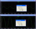
The TINA sim shows negative power regarding the sinewave input; albeit, biased as Vcc/2. This is not possible, and further more I question the 'linear sum' of components...power is a not a linear process.
 

Attachments

mik3

Joined Feb 4, 2008
4,843
I cant see the dc bias on the diagram but according to the outputs it exists.
The power is never going negative!!! This is because the dc bias is greater than the peak value of the ac signal. You see the power fluctuating like a sine wave but this doesnt mean it goes negative because it not the sine wave you know at maths which goes positive and negative around the x-axis (y=0).

Calculate this: a=(Vdc(bias))^2/R3 (your output resistor)

If you draw a line y=a (the result of the above calculation) , this is the line that the output power is fluctuating around.

You can calculate it by finding the average value of the output voltage, then square it and then divide by the output resistor
 

Thread Starter

Distort10n

Joined Dec 25, 2006
429
The DC bias voltage is 5V with a 2Vpp sine wave superimposed on it. So what you are saying is that the total power dissipated in the load is (5Vdc + 1Vrms)^2/8.

What is a little counter-intuitive is that when calulating the power delivered by the supply it is Vdc supply voltage multiplied by the average (not RMS) supply current.
 

mik3

Joined Feb 4, 2008
4,843
The DC bias voltage is 5V with a 2Vpp sine wave superimposed on it. So what you are saying is that the total power dissipated in the load is (5Vdc + 1Vrms)^2/8.

What is a little counter-intuitive is that when calulating the power delivered by the supply it is Vdc supply voltage multiplied by the average (not RMS) supply current.

The RMS value of a 2 Vp-p sine wave is not 1 but it is 0.707. Why you divided it by 8 if you have a 1K resistor in the circuit?

When you calculate the power from the power supply you calculate the average power delivered to the circuit and not the true power. This is because you dont know what is going inside the IC exactly so you cant calculate the true power at every instant.
 

Thread Starter

Distort10n

Joined Dec 25, 2006
429
The RMS value of a 2 Vp-p sine wave is not 1 but it is 0.707. Why you divided it by 8 if you have a 1K resistor in the circuit?

When you calculate the power from the power supply you calculate the average power delivered to the circuit and not the true power. This is because you dont know what is going inside the IC exactly so you cant calculate the true power at every instant.
Oops, nevermind. I am confusing myself this late at night. 1Vrms would be 1.414Vp. The 8 ohm load comes from the fact that the orginal circuit deals with audio.

I am in China, and it is time for bed!
 

mik3

Joined Feb 4, 2008
4,843
Oops, nevermind. I am confusing myself this late at night. 1Vrms would be 1.414Vp. The 8 ohm load comes from the fact that the orginal circuit deals with audio.

I am in China, and it is time for bed!
I made a fault too!! the correct equation for the output power is (Vout(average))^2/R(load) because the output voltage never goes below zero

but this formula is true when you are dealing only with resistors. You said this for an audio system so the load is inductive and not resistive so you have to consider other things in the calculation. Also the output power will vary with frequency. Things get more complicated!!!
 

Audioguru

Joined Dec 20, 2007
11,248
The average voltage of the output is the DC voltage.
The AC changes the voltage momentarily and increases it then decreases it so the average is the DC value.
 

JoeJester

Joined Apr 26, 2005
4,390
Looking at your diagram, the positive peak reading would be 36 mW and the negative peak would be 16 mW. Like audioguru said, the average of the AC component will be zero, so the average power would be 25 mW, the dc bias.

Now if you want to see the changes when using an "simulated" speaker, visit http://www.sound.westhost.com/lr-passive.htm to construct a macro using ESP's speaker model with and without the passive crossovers.
 

Thread Starter

Distort10n

Joined Dec 25, 2006
429
Looking at your diagram, the positive peak reading would be 36 mW and the negative peak would be 16 mW. Like audioguru said, the average of the AC component will be zero, so the average power would be 25 mW, the dc bias.
How can the average power of the AC component be 0? If we eliminated the DC bias or just say 0V DC bias by giving the amplifier dual supplies, this would imply that the average power through the load is 0W. This is not true.

Let us assume a purely resistive load on the output.

I do not agree that the average power is only the DC component. There is a sinusoidal current and voltage flowing through the load along with a constant DC voltage and current.

When I say average power I do not mean the 'arithmetic mean' a.k.a. average, I mean the (Vp*Ip)/2 cos theta or Irms*Vrms power calculations.

It should also be said that the average power is also called the real power and would be equal to the apparent power in a resistive load.

If we give the amplifier a dual supply, then eliminate the DC bias then there is no DC voltage on the output as the AC signal is centered about 0V. The AC signal will rise and fall symetrically about 0V so what is the average voltage/current value? 0? No way.

I will agree that if I integrate instantenous values (which would include positive and negative values) over a full cycle sine wave (0 to 2PI) then the resulting area under the curve is 0. But we are talking about a power calculation for a purely resistive load.

It does not matter what the magnitude is since power is being delivered during both the positive and negative portions of the sine wave. So the average value (arithmetic mean!) for current and voltage waveforms in this case (flipping up the negative cycle to create all positive instantenous values) is .634 of the peak value. But this not represent the heating power in a resistor so we have to use RMS currents and voltages which (without going through the math) is .707 times the peak values.

So coming back to our dual supply with resisitive load, the power in that load is easy to find out.

The hard question is what is the total average power in the load when a DC bias is inserted into the equation?

Superposition will not apply with the power delivered by each source (DC and AC) since power is not a linear process. But currents and voltages can be calculated using superposition and these can lead to a resulting power. So this begs the next question:

Will it be DC voltage/currents + AC average or AC RMS voltages/currents?
 

Audioguru

Joined Dec 20, 2007
11,248
The AC signal increases the power then it decreases the power by the same amount. So the average power is just the DC power. The RMS power is also the DC power.
 

Thread Starter

Distort10n

Joined Dec 25, 2006
429
The AC signal increases the power then it decreases the power by the same amount.
This is incorrect. A purely resitive load will dissipate power regardless of direction. You do not have 'positive' and/or 'negative' real (average) power. The currents and voltages are in phase so when both magnitudes are negative then the product is still positive. The only time there is no power disspated in the load is when voltage and current are 0.

So the average power is just the DC power. The RMS power is also the DC power.
How? Going back to my example with dual supplies to elminate the need of a DC bias in an input, then you are saying that the average power is 0.
 

Ron H

Joined Apr 14, 2005
7,063
When the sinusoidal p-p voltage is small relative to the DC component, average and RMS are close to the same value, but they are not equal. The RMS value will always be higher than the average, because of the nonlinearity incurred in the squaring process (RMS=root mean square, i.e., the square root of the average (mean) squared voltage). The nonlinearity becomes really apparent when you have something like a 2v p-p sine wave, superimposed on 1v DC. See the two plots below, paying attention to the voltage scales on the left. Both have a 1V DC offset, but the sine amplitudes are very different. Notice the differences in distortion of the squared voltages.
 

Attachments

Thread Starter

Distort10n

Joined Dec 25, 2006
429
My equation is wrong then. TINA gives me the same RMS value with a 1Vdc bias and 1Vp signal. I calculate the sum of these: 1.707. So my intergral is wrong.

BTW, broadband in China stinks.

***Gratuitious Update***

I worked it out in integral form. I will have to post later when I get back to the states so someone can check my math.
 

Audioguru

Joined Dec 20, 2007
11,248
I can't believe it.
Wouldn't it be nice if money works the same.
A shopkeeper starts with $100.00 in his store. People buy things and then they return them and get their money back. At the end of the day he has $122.50?
 

Ron H

Joined Apr 14, 2005
7,063
I can't believe it.
Wouldn't it be nice if money works the same.
A shopkeeper starts with $100.00 in his store. People buy things and then they return them and get their money back. At the end of the day he has $122.50?
Don't feel bad. I thought the same thing until I sim'ed it, and then did the math.
Remember that power=(V^2)/R. I posted the V^2 waveform for a 2v p-p sinewave which was offset by 1V. The average of that waveform is 1.5. The square root of 1.5 is 1.2247V. The power is dissipated before the voltage is averaged (duh), hence the distortion. If it worked the other way round (average first), then the waveform superimposed on the DC would be irrelevant. But it doesn't work that way.

V = A + Bsin(x)
V^2 = (A + Bsin(x))^2
expanding,
V^2 = A^2 + 2ABsin(x) + (B^2)/2 * (1 - cos(2x))

When A=B=1 as in the example I posted,

V^2 = 1.5 + 2sin(x) - 0.5cos(2x)

The average (mean) is 1.5.
Sqrt(1.5) = 1.2247
 

Audioguru

Joined Dec 20, 2007
11,248
Hi Ron,
RMS power is supposed to have the same energy as DC power. So a 10VDC supply to a 10V lightbulb and 10VDC modulated with a 10Vp-p sine-wave will make a 10V lightbulb have different brightnesses?
 

mik3

Joined Feb 4, 2008
4,843
Hi Ron,
RMS power is supposed to have the same energy as DC power. So a 10VDC supply to a 10V lightbulb and 10VDC modulated with a 10Vp-p sine-wave will make a 10V lightbulb have different brightnesses?
by modulated you mean superimposed (added)?

if yes, the brightness of the bulb will very sinusoidally but the average brightness per cycle will be the same if the bulb was fed with a 10VDC voltage alone. This is also true for the power, it will vary sinusoidally but the average power per cycle will be as much as if the bulb was driven only by a 10VDC source.

'per cycle' i mean the one complete cycle of the sinusoidal voltage
 

Ron H

Joined Apr 14, 2005
7,063
Hi Ron,
RMS power is supposed to have the same energy as DC power. So a 10VDC supply to a 10V lightbulb and 10VDC modulated with a 10Vp-p sine-wave will make a 10V lightbulb have different brightnesses?
According to the math and the sim, the RMS voltage will be 10.607V.
Mik3, you are wrong. Check out my previous post and do the math.
 

mik3

Joined Feb 4, 2008
4,843
According to the math and the sim, the RMS voltage will be 10.607V.
Mik3, you are wrong. Check out my previous post and do the math.
Ok ron H your calculations are correct but i believe that the real rms voltage is just the value of the DC voltage because always the rms voltage calculations give a bit greater value that the same calculations for the average voltage value , in this case the rms should be the same as the average what do you think?

also the simulation uses these calculations to calculate the rms

check this 4, 5, 6, 7 the average is (4+5+6+7)/4=5.5
the rms = sqrt((4^2+5^2+6^2+7^2)/4) = 5.56

the result should be the same but there is a small difference because of the squares
 
Top