Op Amp LM339

Thread Starter

Tomnbon3

Joined Jan 17, 2018
5
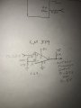
I’m trying to use an LM339 as a voltage comparator to translate a 0-2.5 volt DC level into 0-5 volt logic level. With a 1.6 volt reference on the negative input created with a 100k and 47k divider and 2.5 volts on the positive input, the output will only go to 2.5 volts even with a 1k pull-up to 5 volts on the output. What am I doing wrong?
 

Thread Starter

Tomnbon3

Joined Jan 17, 2018
5
It should go to 5V.
Do you have any other load on the output?
Thanks for the reply! No just the pull up resistor and I’ve tried 330 ohms up to 100k. What’s strange is that on the bench test the output goes to 5 volts with a separate 0-2.5 volt dc signal but when connected to the unit I’m trying to interface with and using its internal 5 volt supply and 0 to 2.5 volt dc signal out, the op amp will only go to 0 or 2.5 volts. I’ve tried that same signal connected to a CMOS gate and get the same results (which didn’t surprise me).
 

crutschow

Joined Mar 14, 2008
38,506
but when connected to the unit I’m trying to interface with and using its internal 5 volt supply and 0 to 2.5 volt dc signal out, the op amp will only go to 0 or 2.5 volts.
Then there's something funny about the interface to the circuit.
Have you measured all the voltages to be sure they are correct?
Do you have an oscilloscope to look at the signals?

Incidentally, the LM339 is a comparator, not an op amp.
 

MrChips

Joined Oct 2, 2009
34,812
Some possibilites:

1. Something is not right with your wiring.
2. Something is wrong with your +5V power source.
3. The chip is bad.

Post a photo of your setup so that we can have a closer look.
 

absf

Joined Dec 29, 2010
1,968
I agree with the conclusions drawn by MrChips....

And here's the sim with 339 side by side with 324. Both work even without the positive FB on 324. (forget the name. Was it hysteresis?)

AAC_tomnbon3.PNG
 

dendad

Joined Feb 20, 2016
4,637
but when connected to the unit I’m trying to interface with and using its internal 5 volt supply and 0 to 2.5 volt dc signal out, the op amp will only go to 0 or 2.5 volts.
You start by saying you only have the pullup then you say the above.
What are you connecting it to? Is the "unit" the load or the circuit shown?
For example, Is it an opto input? If so, the LED will limit the volts.
If it is the same as your diagram, it sounds like you have a faulty part or wiring problem.
 
Last edited:

Thread Starter

Tomnbon3

Joined Jan 17, 2018
5
There are many replies to my request for help, I’ll try to answer.
I do have an oscilloscope but the levels are clean without observed noise. I monitor the 0-2.5 volt signal and 5 volt power supply while performing the tests. Both are steady and consistent without any loading from the comparator and it’s external resistors. I’m trying to interface with a Whitfield pellet stove in order to externally control the heat output via a 3 stage thermostat. The heat output of the pellet stove is currently controlled by pressing a switch that selects low-medium-high heat. The stove internally outputs 0 volts, 2.5 volts and 5 volts to select the three heat levels. I am trying to interpret those levels in order to gain control of the heat levels. However, I keep running into this previously described limitation. My sampling points are at an internal voltage/LED ladder. There are three LED’s to represent the low setting, then these three plus three (6) for medium, then three more (9) for high (0v, 2.5v and 5v) So the reply from Dendad asked about LED’s and the answer is yes. If this is the problem, is there a solution?
 

crutschow

Joined Mar 14, 2008
38,506
When the output is 2.5V is anything connected to the LM339 output besides the pull-up resistor?
Are you sure the output resistor is connected to a solid 5V?
 

WBahn

Joined Mar 31, 2012
32,836
Measure the voltage across the resistor and make sure it's 2.5 V. If it isn't, then you might have a bad connection that is resulting in a high resistance pullup. Cleaning up the connection will solve the problem. If it is, then it indicates that the part is actively pulling down on the output when it shouldn't be.

What about the other three comparators in the package? Have you tried all of them? It could be that only one of the four is bad. Are all of them properly connected -- i.e., no floating inputs? Since all four on physically on the same die, letting the others behave in an undefined state can affect the behavior of the one you are trying to use.

Replace the 1 kΩ pullup with a 100 ohm resistor and see if the output voltage is closer to the 2.5 V mark or the 5 V mark. It doesn't really matter, truth be told, because in either case something is wrong. But this will pretty well confirm that the problem is with the part.
 

sghioto

Joined Dec 31, 2017
8,634
Output follows input. Whmmmm sounds like input is PWM, though he states it is not but it works on the bench using external DC source. Go figure.
Steve G
 

BobTPH

Joined Jun 5, 2013
11,515
I’ve tried that same signal connected to a CMOS gate and get the same results (which didn’t surprise me).
I missed this part before. A CMOS gate would never output a stable 2.5V with a 5V supply.

Now I am convinced that the signal is a 50% duty cycle 0-5V square wave.

Bob
 

MrChips

Joined Oct 2, 2009
34,812
I missed this part before. A CMOS gate would never output a stable 2.5V with a 5V supply.

Now I am convinced that the signal is a 50% duty cycle 0-5V square wave.

Bob
Aha!

Is the TS measuring the output voltage with a DDM?:rolleyes:

Good eye Bob.
 

WBahn

Joined Mar 31, 2012
32,836
There are many replies to my request for help, I’ll try to answer.
I do have an oscilloscope but the levels are clean without observed noise. I monitor the 0-2.5 volt signal and 5 volt power supply while performing the tests. Both are steady and consistent without any loading from the comparator and it’s external resistors. I’m trying to interface with a Whitfield pellet stove in order to externally control the heat output via a 3 stage thermostat. The heat output of the pellet stove is currently controlled by pressing a switch that selects low-medium-high heat. The stove internally outputs 0 volts, 2.5 volts and 5 volts to select the three heat levels. I am trying to interpret those levels in order to gain control of the heat levels. However, I keep running into this previously described limitation. My sampling points are at an internal voltage/LED ladder. There are three LED’s to represent the low setting, then these three plus three (6) for medium, then three more (9) for high (0v, 2.5v and 5v) So the reply from Dendad asked about LED’s and the answer is yes. If this is the problem, is there a solution?
You really need to post a schematic that includes everything that touches this circuit, including those LEDs that you are talking about. Indicate where on that schematic you are measuring input and output voltages. It would also be could to post pictures of your o-scope input/output waveforms.
 
Top