OOK Demodualtor Envelope Detector

Thread Starter

ranaiftikhar

Joined Nov 1, 2016
42
Hi
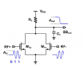
I am working on simple envelope detector. can any one help me from where can i read the details of the envelope detector mentioned in attached figure. i found this basic circuit in paper but not succeed to get the therory part of it to understand completely. Thanks in advance.

upload_2016-11-2_12-10-27.png

I got this simple circuit in

X. Yu, H. Rashtian, S. Mirabbasi, P. P. Pande and D. Heo, "An 18.7-Gb/s 60-GHz OOK Demodulator in 65-nm CMOS for Wireless Network-on-Chip," in IEEE Transactions on Circuits and Systems I: Regular Papers, vol. 62, no. 3, pp. 799-806, March 2015.
 

Attachments

AlbertHall

Joined Jun 4, 2014
12,346
When there is no input signal both M1p and M1n will be switched off and so the output will be high. During one half cycle of the input waveform M1p will conduct and during the other half cycle M1n will conduct. While either of them is conducting the output will be low. The capacitor CL will smooth the output waveform and maintain the low level output at the zero crossings of the input waveform.
 

AnalogKid

Joined Aug 1, 2013
11,048
The circuit is acting as an inverting full-wave rectifier of the incoming AC envelope. This doubles the ripple frequency into the filter capacitor, so for a specified ripple p-p amplitude this circuit needs a smaller capacitor than would a simple diode AM detector.

Note that this circuit is used in integrated circuit design, not discrete component design. Those people often do strange things because of the limited component structures they have to work with.

ak
 

mswhin63

Joined Sep 19, 2012
1
In the initial condition when there is no signal the FET's used are off, thus the voltage output is VCC.

The signal input is cos(2*pi*f*t) + (-cos(2*pi*f*t)) = (simply -> cos(a) - cos(a) = 0

There is the one zero output (notice the rectification occurs at the zero volt level) , finally the RC values are not really required other than to take up the slack of inefficiencies in the components and possible non matching.

The system is design for 60GHz so RC does not require to be very large at all.
 

Thread Starter

ranaiftikhar

Joined Nov 1, 2016
42
In the initial condition when there is no signal the FET's used are off, thus the voltage output is VCC.

The signal input is cos(2*pi*f*t) + (-cos(2*pi*f*t)) = (simply -> cos(a) - cos(a) = 0

There is the one zero output (notice the rectification occurs at the zero volt level) , finally the RC values are not really required other than to take up the slack of inefficiencies in the components and possible non matching.

The system is design for 60GHz so RC does not require to be very large at all.
 

AnalogKid

Joined Aug 1, 2013
11,048
Almost. It could be a "singly-balanced" (straight-AM) modulator if you un-ground the two sources and drive that node with the modulating signal. That is basically the front end of the LM13700 VCA (voltage controlled amplifier). Doubly-balanced is more common in RF and comm chip designs because it can do many more comm functions. The MC1496 is the classic part. Here are some doubly-balanced circuits.

ak
 
Last edited:

Thread Starter

ranaiftikhar

Joined Nov 1, 2016
42
hi everyone

Its great understanding from above posts. Thanks for your time.

I have one more question about the spectrum of the OOK transmitter with random base band signal.

Thanks
 
Top