NTC Project (Wheatstone Bridge + Instrumentation Amplifier) - Stuck!

Thread Starter

jonaas18

Joined Apr 4, 2019
67
I'm creating a thermometer (using an NTC thermistor) for my college project. I began to analyze my sensor in terms of its linearity, temperature range, etc (specifications in general) ... For this project, I decided to use a temperature range from 55ºC to 150ºC (celsius).

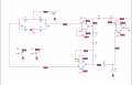
Afterwards, I implemented my sensor in a wheatstone bridge. In order to do so, I defined my lowest temperature (55ºC) resistance value (2989 Ohms) and my highest temperature (150ºC) resistance value (182.6 Ohms). I proceeded to find the value of the other 3 resistances so I could end up with a [0 ---- 5] voltage at the end of my bridge (beeing 0V to 182.6 Ohms and 5V to 2989).

My biggest problem now is implementing an I.A.:

My current wheatstone bridge voltage ranges from -13mV to 5.05V which is fine (tho I'm currently designing a gain = 2x I.A. and I'll then throw it back to my voltage range by using a summing amplifier in order to reduce circuit's noise). Thing is, I'm not able to have 2x my bridge's voltage at the end of my I.A. (even tough I'm following the I.A. equation in order to find it's gain).

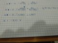
As you can see, I simply defined the same value for every resistance besides the middle one (this should mean that (1+(2*Any-other-resistance / Rmiddle)) * (V+ - V-) = 2(V+ - V-), which should define a voltage range of [-0,0026 ---- 10,1]V).

Note: I'm using TL084's to build my I.A. (tho I'm testing some other components like TL082 or LM324)

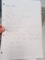
There's a picture attached as I know I messed up explaining this. Any help would be appreciated. I'm really stuck and I have no idea what's the problem (also thought it might be balancing the bridge or having high voltage on my op amps but atm I'm just throwing possibilities into the air without any thinking).
 

Attachments

ericgibbs

Joined Jan 29, 2010
18,766
hi jonaas,
Welcome to AAC.

Your basic LM324, IA build looks OK, I assume you have used at least 1% value resistors, preferably 0.1%.

The bridge is too far off balance, you are showing a 5V differential signal at the IA inputs. I suggest you recalculate the R2 value.

Do you have a graph or part number for the thermistor you could post.?

E
 

Thread Starter

jonaas18

Joined Apr 4, 2019
67
I really can't post a graphic right no (on my Phone) but the thermistor is the NTC100E31303JBO.

How is the bridge wrong calculated? I figured it could be that but I really don't know how to balance it if I have a constantly changing sensor resistance. Searched on some websites and on my teacher's notes, nothing really teaches how to do it. He simply throws old examples in there.
 

Thread Starter

jonaas18

Joined Apr 4, 2019
67
Yes. My idea is to have a temperature range of 55.C to 150.C, with, accordingly, 5V to 0V, leaving the bridge. Then, after the I.A., I should have the same voltage range as leaving the bridge (or different, as I am using atm. I will then use other amplifiers to tone it down) Important part is, I will definitly invert it while using another amplifier in the future, so I would have 55.c at 0V and 150.c at 5V. You could probably invert the gain on the I. A. itself but I kinda did it like this so I would understand every step.

As for the resistances, here is my math:

Vcb = 15. ( (R2/R1+R2) - (R3/R3+RT))

Then, if Vcb =0v means 150.C, this means RT=182.6 (ntc datasheet).
And, if Vcb =5v means 55.C, this means RT=2989 (ntc datasheet).

Given this,

0 = 15. ( (R2/R1+R2) - (R3/R3+182,6))
5 = 15. ( (R2/R1+R2) - (R3/R3+2989))

Then, I simply threw in values,

If R3 = 5030 ohms,
R2 = 27,38R1 or R2 = 23,5R1 (2 solutions as I have 2 equations above)

If R1 = 5030 ohms,
R2 = 136k or R2 = 117k (2 solutions as I have 2 equations above)

Choosing a value between those 2 values,

If R2 = 135k,

Vcb = - 13mV
Vcb = 5,05 mV

(did this by replacing the resistances on the first equations i wrote and finding the final value of Vcb according to RT = 182.6 ohms and RT = 2989)
 

Attachments

ericgibbs

Joined Jan 29, 2010
18,766
hi j,
Consider this, say you made R2 the same value as the Rt value at +55C.
Think, in which arm of the bridge the thermistor was placed, would give a rising positive differential voltage as the Rt value falls with rising temperature.
Consider pin #3 of the IA .

As it is Homework I can only give you hints.
E
 

Thread Starter

jonaas18

Joined Apr 4, 2019
67
Supposedly, the right lower arm. If RT goes down by using a voltage divider, less voltage geta caught up on RT, so by common sense, the voltage around R3 rises up to compensate RT as Vrt + Vr3 = 15
 

ericgibbs

Joined Jan 29, 2010
18,766
hi,
So what do you calculate the bridge differential output voltage range from +55C to +150C [ you know the Rth values for those two points]
As a starter at 55C it should be 0V... so what will it be at +150C.?

E
 

Thread Starter

jonaas18

Joined Apr 4, 2019
67
Ahh got it. So at 55.C the bridge is balanced, so, the output is 0v. If RT is 182.6 tho, the output voltage will be:


If R1 = R3 and R2 = 2989 (with RT = 182.6), Vcb = - 8.61.
I meant to write R1 = R3 = 4700 on the image above. There is a mistake there
 

Thread Starter

jonaas18

Joined Apr 4, 2019
67
If R1 = R3 = 4.7k, Vcb is - 8.61 again. If I change the resistance values however, the voltage is different Perhaps I can use R1=R3=zzz in order to have an output = 5v?? That would mean that R1 = R3 = 2.1k. Meaning a - 4.99V
 

ericgibbs

Joined Jan 29, 2010
18,766
Do you have the option of reducing the Vext [+15V] to a lower value.?
Consider the effect that would have on the max Vout of the bridge,??

E
This LTS sim shows the result you have calculated.
 

Attachments

Thread Starter

jonaas18

Joined Apr 4, 2019
67
Yes I can. If I reduce my voltage source that would mean a lower voltage output on the bridge right?

On what would that help? (Also didn't understood if my calcs with R1 = R3 = 2.1k, R3 = 2989, RT = 182.6 were wrong or not)
 

Thread Starter

jonaas18

Joined Apr 4, 2019
67
Ahh .. Im not really following ... You can extract the bridge equation:

Vdif = V ( (R2/R1+R2) - (R3/R3+RT) )

We are considering R2 = 2989. At 55.C I understand that the bridge is balanced. For 150.C, RT = 182. This means,

Vdif = 15.( (2989/R1+2989) - (R3/R3+182)
Right?

Now, if we change R1 and R3 values, Vdif will change aswell. How did you get to the 7,5 and did you allocated 2989 ohms to R3 by random or because of smth in particular?
Forget it. I understand the 7.5 value. But it should be 15.(7,5 - 2989/2989+182) as I am calculating Vdif from left to write. But yea sure. Understood it.
 
Top