Noise in phono preamp - stereo to mono

Thread Starter

mzinys

Joined Mar 8, 2017
4
Hello people,

I am designing a kind of a preamp, which has a stereo phono input that has to be mixed down to mono. For the phono stage i'll be using VSPS from RJM audio (http://phonoclone.com/diy-pho5.html) and for the mixing part, a simple virtual ground op amp mixer.

Two possible variations here:
1) Mix phono signals, and RIAA amplify them;
2) RIAA amplify phono signals, then mix;

Now common sense tells me, that the amplification should take part before the mixing, because otherwise, the additional noise introduced by the mixing op amp and resistors would be amplified greatly by the phono stage, which has gain of around 40dB.

But then i'd have to build two separate phono stages, and that implies two things: 1)Combined noise from the two stages will be somewhat higher than from a single stage; 2) Component tolerance differences in the two stages may lead to inaccurate equalisation when mixed.

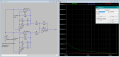
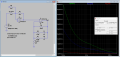
So I decided to try to simulate the thing in LTSpice and was surprised with the results. The simulated noise density in 2nd configuration happens to be many times (to be exact, 150 times at 1kHz) greater than that of the 1st configuration.
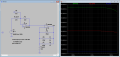
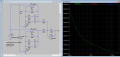
upload_2017-3-24_19-2-29.png


upload_2017-3-24_19-2-49.png

Also what is very strange is the different noise contribution of the input and gain set resistors...

Maybe there is something wrong in the way i did the simulation? Any comments welcome, thanks
 

GopherT

Joined Nov 23, 2012
8,009
You need a compensation resistor on the non-inverting input of the ne5532. There is significant current flow into a bjt op amp so it helps balance.

Also, your input and feedback resistors should be divided by 10 for lower noise. A 4.7k instead of 47k and 75k instead of 750k.

Edit: from datasheet...

Because the transfer function of VOUT– is heavily reliant on resistors (R1, R2, R3, and R4), use resistors with low tolerances to maximize performance and minimize error. This design used resistors with resistance values of 36 kΩ with tolerances measured to be within 2%. But, if the noise of the system is a key parameter, the user can select smaller resistance values (6 kΩ or lower) to keep the overall system noise low. This ensures that the noise from the resistors is lower than the amplifier noise.
 
Last edited:

Thread Starter

mzinys

Joined Mar 8, 2017
4
You need a compensation resistor on the non-inverting input of the ne5532. There is significant current flow into a bjt op amp so it helps balance.g
That's a good guess but actually it increases noise even further.

As for the high resitances used, there are two reasons:
For the amplifier, the gain has to be quite high (40-50 dB). Lowering the 750k would mean the 470R(R_gain) should also be reduced, and going below 220R is not okay i suppose? Also, the transfer function must follow RIAA curve, so by changing the 750k I would mess it up.

As for the mixing resistors (R_input), the value can not be lowered because of the phono cartridge loading (signal source is directly loaded by them, as the current flows into the virtual ground), which is 47k recommended. Lowering the values may introduce higher distortion.

Anyway, switching to 2134 opamps in the simulation produced the expected results. I'll post some screenshots later today.

Thanks!
 

Thread Starter

mzinys

Joined Mar 8, 2017
4
Hello again people,

So as I mentioned before I substituted the NE5532's in my simulations with 2134's and that changed the thing quite a lot.
Here are the graphs:
upload_2017-3-25_22-13-45.png
upload_2017-3-25_22-13-59.png

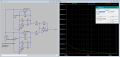
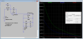
Now, the noise in the 'mix first' configuration clearly has more noise at the output compared to the 'amplify first' configuration (which is kind of common sense isn't it).

Still there is one strange thing that i don't understand: Note the R_input in the 'amplify first' graph. What is strange to me that the noise density = 0 nV/Hz^1/2, throughout the whole spectrum! How is it possible? I mean the resistor must have it's Johnson's noise, and it should be amplified by the 40+ dB of the preamp... still it shows 0.

Any ideas how?
Anybody?

regards,
Mangis
 

Attachments

GopherT

Joined Nov 23, 2012
8,009
That's a good guess but actually it increases noise even further.

As for the high resitances used, there are two reasons:
For the amplifier, the gain has to be quite high (40-50 dB). Lowering the 750k would mean the 470R(R_gain) should also be reduced, and going below 220R is not okay i suppose? Also, the transfer function must follow RIAA curve, so by changing the 750k I would mess it up.

As for the mixing resistors (R_input), the value can not be lowered because of the phono cartridge loading (signal source is directly loaded by them, as the current flows into the virtual ground), which is 47k recommended. Lowering the values may introduce higher distortion.

Anyway, switching to 2134 opamps in the simulation produced the expected results. I'll post some screenshots later today.

Thanks!

Guess? No.

Your simulation has its own inaccuracies. Try a breadboard.
 

Thread Starter

mzinys

Joined Mar 8, 2017
4
Guess? No.

Your simulation has its own inaccuracies. Try a breadboard.
I have tried the breadboard previously and the 'amp first' config is clearly better. Anyway in both reality and simulation, the input resistor on the +in of 5532 does not make a difference, and i think that's because of the internal resistance of the phono cartrige (which is in the vicinity of 2k). So that kind of is a guess.

Anyway what's intresting to me here is the simulation results, and the correct way to run the simulation. I assume I'm not doing it right as the results are somewhat strange, as already mentioned with the 47k R_input (across the input and ground) which simulates to 0 nV/Hz^1/2.

EDIT:

Tried to change the series resistance of the signal source in the simulation to 1.2k, and suddenly the input 47k resistor has some noise to it. Now it's clear to me what was wrong.
 
Last edited:
Top