Remember that "ground" in these circuits is merely a way of assigning a specific voltage to a specific node. It has NO intrinsic meaning beyond that.
Voltages are ALWAYS a difference in potential between two points. So the only way we can talk about the voltage AT a particular point is to arbitrarily define the voltage as SOME point to be SOME particular value. We COULD pick the lower left corner and declare it to be 1317 V and proceed from there just fine. But humans have less difficult overall if we pick one of the nodes and declare it to be 0 V. The voltage on all other nodes is then simply the voltage difference between that node and the node we assigned 0 V to (which we often -- and in most circumstances improperly, as it turns out -- call "ground").
When you do node voltage analysis, if you have six nodes, you get one free because you get to call it 0 V. You then have to write node equations for the other five and solve them.
Oh you can use any method but I used node voltage for it cause super position or mesh analysis could have been really long. And do you mind checking my equations, it's just my freshman year in college and these concepts were introduced to us on day 2 itself.
Superposition is probably the quickest and easiest for this circuit.
Mesh analysis is also straightforward because one mesh current is trivial and the other three meshes have easily accounted for voltage sources.
Using nodal analysis, dealing with voltage sources usually ends up requiring the use of supernodes and auxiliary equations. That's the case here, although it's not too bad since two of the voltage sources are ground-referenced.
I'll look at your equations if you will rewrite them so as to properly track your units. That's for your own good. You should get in the habit of properly tracking your units from beginning to end of every computation you do. Most mistakes you make will mess up the units (unfortunately, not all of them) and so when the units stop working out, you know you've made a mistake and any further work is guaranteed to be wrong. I can't even count the number of times someone has made a mistake in setting up their basic equations and then proceeded to do several pages of totally worthless work when, had they tracked their units, their very first line of work would have screamed out that it had an error in it.
Since you appear to have gotten answers for the node voltages, you are in a position to determine if your answer is correct based on the answer itself.
Use those voltages to find the currents in all of the resistors and then use KCL to find the current in the 12 V supply. Then see if the currents satisfy KCL at the bottom-middle node (the output of the current source). If they do (within roundoff error), you almost certainly got the correct result. If they don't, you did something wrong.
If you will do these two things habitually (tracking your units step-by-step and verifying that the answer is correct based on the answer itself), you will find that your grades will shoot through the roof. These are extremely powerful error detection tools available to the engineer. They will save you lots of time and embarrassment (and possibly getting fired or even killing someone) once you are out in the real world.
While analyzing the circuit again using a different technique is one way to verify an answer, that is not what I was suggesting. What I'm recommending is that you use your answers to directly determine if they are the solution by applying them to the problem. For example, take the original problem and pretend that the value of the current source wasn't given but that the value of the node voltages was (and were equal to the values you found). Use them to figure out what the value of the current source is. Then see if that matches what it's supposed to be. This should be a much faster process than reanalyzing the circuit using a different technique, particularly since if you chose the best technique to use the first time, the reanalysis will take longer than the original analysis did.
Your mesh current setup is for a completely different circuit -- namely one in which the 3.4 V source has been mysteriously removed.
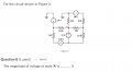
Also, don't throw away information about polarity by only calculating the magnitude of the voltage across the component. The sign of the answer is THE most significant "digit" in the answer -- voltages and currents are both signed quantities, so be sure that that is included in your verification process. That was one thing that bothered me when I first saw the question because it is only asking for the magnitude of the voltage at Node A, when it should simply ask for the voltage at Node A.
Thank you for tracking your units. Note that in your node voltage equations where you have all of the "1 Ω" terms in the denominator that if you multiply both sides of the equation by 1 Ω that the units for each term on the left become just voltage (due to the variables) and on the right they also become voltage since (A·Ω) yields (V).
Also, unless there is a reason to do otherwise, answers should only be reported to three sig figs. It is actually unusual that we are justified in reporting them to more than two sig figs since that indicates that we are claiming to know the answer to about 1% while the tolerances on our components are typically 5% or worse. Keeping one or two additional sig figs for intermediate results is fine to avoid excessive roundoff error accumulation. Also, it is common practice to report an answer that begins with a 1 to four sig figs (or, said another way, to not count a leading 1 as a significant figure, although that's not what's really happening).
While analyzing the circuit again using a different technique is one way to verify an answer, that is not what I was suggesting. What I'm recommending is that you use your answers to directly determine if they are the solution by applying them to the problem. For example, take the original problem and pretend that the value of the current source wasn't given but that the value of the node voltages was (and were equal to the values you found). Use them to figure out what the value of the current source is. Then see if that matches what it's supposed to be. This should be a much faster process than reanalyzing the circuit using a different technique, particularly since if you chose the best technique to use the first time, the reanalysis will take longer than the original analysis did.
Here's what I'm talking about when I say use your answers to verify their correctness from the problem itself.
I've annotated the known voltages, including your answers via nodal analysis.
Using nothing but Ohm's Law, you can calculate the blue and the green currents.
Then, using the blue currents and KCL, you can easily calculate the orange current.
Then, using the orange and the green current, you can use KCL to determine what the current in the current source is (which we are pretending we don't know).
If that doesn't come out very close to 2.5 A, then something is wrong.
One thing that is very important and that I didn't mention: When you do this, do not use ANY part of the work that you did in obtaining your original answers. For instance, if one of your intermediate results was finding the current in, say, the 1.5 Ω resistor, do NOT use that current as the green current above. Doing so risks applying a mistake that you made back into the verification in such a way as to make it seem like your answers are consistent with the problem, but only because you essentially have two mistakes that offset each other. You really do need to apply only your answers to the original problem statement and then go from there.
Your mesh current setup is for a completely different circuit -- namely one in which the 3.4 V source has been mysteriously removed.
Also, don't throw away information about polarity by only calculating the magnitude of the voltage across the component. The sign of the answer is THE most significant "digit" in the answer -- voltages and currents are both signed quantities, so be sure that that is included in your verification process. That was one thing that bothered me when I first saw the question because it is only asking for the magnitude of the voltage at Node A, when it should simply ask for the voltage at Node A.
Thank you for tracking your units. Note that in your node voltage equations where you have all of the "1 Ω" terms in the denominator that if you multiply both sides of the equation by 1 Ω that the units for each term on the left become just voltage (due to the variables) and on the right they also become voltage since (A·Ω) yields (V).
Also, unless there is a reason to do otherwise, answers should only be reported to three sig figs. It is actually unusual that we are justified in reporting them to more than two sig figs since that indicates that we are claiming to know the answer to about 1% while the tolerances on our components are typically 5% or worse. Keeping one or two additional sig figs for intermediate results is fine to avoid excessive roundoff error accumulation. Also, it is common practice to report an answer that begins with a 1 to four sig figs (or, said another way, to not count a leading 1 as a significant figure, although that's not what's really happening).
Yes thank you for letting me know that I would have to consider the 3.4 V source too. From now now on I'll surely keep the track of units all the time. Yes I did read upon answering questions with significant digits which explained me that our calculations cannot be more accurate than the significant digits provided in the question and suggested even giving an expected error range while answering question. However our teacher here wants us to report the answer to four decimal places but I'll surely keep this information in my mind.
I've annotated the known voltages, including your answers via nodal analysis.
Using nothing but Ohm's Law, you can calculate the blue and the green currents.
Then, using the blue currents and KCL, you can easily calculate the orange current.
Then, using the orange and the green current, you can use KCL to determine what the current in the current source is (which we are pretending we don't know).
If that doesn't come out very close to 2.5 A, then something is wrong.
One thing that is very important and that I didn't mention: When you do this, do not use ANY part of the work that you did in obtaining your original answers. For instance, if one of your intermediate results was finding the current in, say, the 1.5 Ω resistor, do NOT use that current as the green current above. Doing so risks applying a mistake that you made back into the verification in such a way as to make it seem like your answers are consistent with the problem, but only because you essentially have two mistakes that offset each other. You really do need to apply only your answers to the original problem statement and then go from there.
Thanks a lot of providing me the detailed step by step method, I just worked upon this and verified it with KCL. This would have not possible without your guidance, I didn't want to loose interest in this subject. But by applying the concepts from the basics and using fundamentals has invoked my curiosity for it again. I am really grateful for your support and hope to use this great forum again when I am again stuck with a genuine problem.
Yes thank you for letting me know that I would have to consider the 3.4 V source too. From now now on I'll surely keep the track of units all the time. Yes I did read upon answering questions with significant digits which explained me that our calculations cannot be more accurate than the significant digits provided in the question and suggested even giving an expected error range while answering question. However our teacher here wants us to report the answer to four decimal places but I'll surely keep this information in my mind.
Definitely report answers to the level requested by the instructor -- if nothing else, that falls under the heading of the proper care and feeding of homework graders.
The proper way to do it is to take into account the uncertainties in each value and propagate them through to the answer. That's the "physics" way, but the "engineering" way is more relaxed because we know that for the values we have in the real world, reporting three sig figs is almost always "good enough".
I don't like rules like "to four decimal places" because that means that you would have to report a large voltage to an unreasonably large number of sig figs (like 4325.3972 V) while small voltages would be reported to an unreasonably small number of sig figs (like 0.0004 V). It's also ambiguous when prefixes are used. For instance, that last example might have been 421.9628 µA or 0.4219 mA. So what is really being requested. If, instead, you were told to report them to three sig figs, you get the same value in each case, namely 0.000422 A, 0.422 mA, 422 µA.
You might mention this, gently, to the instructor. Don't come across as trying to correct them (some instructors take that very poorly, which actually reflects very poorly upon them, but that doesn't help you should they take it out on you). Instead, tell them that you are unclear about this and are asking for clarification.
Thanks a lot of providing me the detailed step by step method, I just worked upon this and verified it with KCL. This would have not possible without your guidance, I didn't want to loose interest in this subject. But by applying the concepts from the basics and using fundamentals has invoked my curiosity for it again. I am really grateful for your support and hope to use this great forum again when I am again stuck with a genuine problem.
As a gentle poke -- I see a lot of stuff in your doodling that lack units. I really, really am recommending that ANY time you write down a value that represents a physical quantity with units, that you include the proper units. You want to get so much in the habit of this that you are downright uncomfortable working with numbers that don't have units (when they should). It's at this point that the process becomes so engrained that you don't even think about it and that units discrepancies jump out at you without you even looking for them. I've gotten to the point where I simply can't work a problem that is not dimensionally consistent and will have to figure out and add in the missing units before I can proceed. But it is SO worth it, since I can't count the number of times, even in the last month, that tracking units has allowed me to catch silly (and not so silly) mistakes I have made. In fact, when I solved this problem, I made a common blunder and caught it immediately because the units got messed up.
Definitely report answers to the level requested by the instructor -- if nothing else, that falls under the heading of the proper care and feeding of homework graders.
The proper way to do it is to take into account the uncertainties in each value and propagate them through to the answer. That's the "physics" way, but the "engineering" way is more relaxed because we know that for the values we have in the real world, reporting three sig figs is almost always "good enough".
I don't like rules like "to four decimal places" because that means that you would have to report a large voltage to an unreasonably large number of sig figs (like 4325.3972 V) while small voltages would be reported to an unreasonably small number of sig figs (like 0.0004 V). It's also ambiguous when prefixes are used. For instance, that last example might have been 421.9628 µA or 0.4219 mA. So what is really being requested. If, instead, you were told to report them to three sig figs, you get the same value in each case, namely 0.000422 A, 0.422 mA, 422 µA.
You might mention this, gently, to the instructor. Don't come across as trying to correct them (some instructors take that very poorly, which actually reflects very poorly upon them, but that doesn't help you should they take it out on you). Instead, tell them that you are unclear about this and are asking for clarification.
Yes it's true, reporting answers to four decimal places does not make a lot of sense in most of the scenarios. I surely would try to politely ask for an explanation from my instructor regarding the same.
As a gentle poke -- I see a lot of stuff in your doodling that lack units. I really, really am recommending that ANY time you write down a value that represents a physical quantity with units, that you include the proper units. You want to get so much in the habit of this that you are downright uncomfortable working with numbers that don't have units (when they should). It's at this point that the process becomes so engrained that you don't even think about it and that units discrepancies jump out at you without you even looking for them. I've gotten to the point where I simply can't work a problem that is not dimensionally consistent and will have to figure out and add in the missing units before I can proceed. But it is SO worth it, since I can't count the number of times, even in the last month, that tracking units has allowed me to catch silly (and not so silly) mistakes I have made. In fact, when I solved this problem, I made a common blunder and caught it immediately because the units got messed up.
Right I would keep this advice in my mind and I know the units would become more important as we approach more complex and real-time problems. Right now the instructor is just trying to teach us basics on network problems but as an engineer I would always keep a track of these units.
Right I would keep this advice in my mind and I know the units would become more important as we approach more complex and real-time problems. Right now the instructor is just trying to teach us basics on network problems but as an engineer I would always keep a track of these units.
Don't kid yourself. As an engineer you will do what you've trained yourself to do, which is why most engineers do not properly track their units. Put yourself a step ahead and start training yourself to do it today.
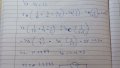
I hope you're not going to turn in something that looks like the image in post #1. I can't even tell that you fully understand how nodal analysis is done. Here are some of the constructive criticisms I have for your work. You should show the nodal equations in their most fundamental form as a sum of terms equal to zero. Once done, then you can collect terms and simplify.
 Facebook
 Google
 GitHub
 Linkedin
 242.4 KB Views: 35