Facebook
 Google
 GitHub
 Linkedin

No start. Cranks good & strong.
Checking for spark.
All alone here, no one to help me, so I am jumping both the starter relay & the ASD relay, instead of turning the main switch.
Specifics: #30 is jumped to #32, & #60 is jumped to #62.
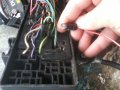
My test light shows voltage at the green-orange wire at the connection at the coil pack.
Spark plug is hand-held against ground.
Result: no sign of spark.
What gives?
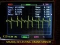
Everything is connected. Crankshaft sensor, etc.
By keying on, and jumping just the starter relay, the ASD should pull in by itself. If the ASD is not pulling in via the PCM, then there is potentially no cam crank sync. If there is no sync, there will never be any spark or injector pulse.
The better thing to check at the coil is the two grounds, to see if the PCM is switching ground on and off. You should be able to do this by back probing the connector with a paperclip, and using a test light. If the PCM is switching ground, and the coil has 12 volts, then possibly the coil got damaged somehow.
Ignition coil number 1 and number 2 drivers. They switch the coils to ground, creating current flow, energizing the coils. when the PCM switches the ground path off, the coil's magnetic field collapses, creating the spark.
Today I tested continuity on all wires for both the crank & cam sensor, & also the coil pack. All have continuity.
The method I used was ohmmeter, with its two probes, one on sensor end, the other on the PCM end. Zero ohms for all.
How can I tell if the coil pack is being energized?
Also I tested for voltage on the crank & cam sensors, but my voltmeter indicated zero volts while the engine was being cranked.
The method I used was voltmeter, with its two probes, one on sensor end, the other on ground end.
Today i ordered a new Ignition Coil Pack.
Update: still no spark, even with the new Ignition Coil Pack.
The coil driver grounds are the pcm ground. That is the one ground point right behind the left headlight. If the pcm is not getting it's ground, it will not be able to provide grounds to the circuits that need them to work.The ground on the control side of the relays are controlled by the pcm. It provides ground to actuate the asd, fuel pump, starter, and other relays.
Update: That ground is intact.
Today my test light remained a steady light while probing both of the two driver wires on the coil pack. This is, rather than the orange wire in the middle.
When I disconnected the wire harness from the coil pack, I probed, with my test light, the two driver wires, and my test light indicated zero voltage for both the two driver wires.
These two driver wires are known as "Coil Negative" and a pulsating light would indicate normal operation. But my test light remained a constant or steady light for both the two driver wires. The coil pack is brand new, so I think i have a driver or transistor problem.
No flicker means no control, on either of the "Coil Negative" or driver wires.
A jumper wire is connecting the dark green & orange wire with the B+ wire.
Today I checked the ASD relay and the fuel pump relay.
When i set a jumper wire from ground to the brown wire that runs from the ASD relay to the PCM., which the fuel pump relay clicked like mad, and the fuel pump sounded up, pressurizing the fuel.
The ASD relay sounded off clicking when i set a jumper wire from ground to the blue & yellow wire that runs from the ASD relay to the PCM. This caused the green & orange wire to go live to the ignition coils.
Also I ordered a used PCM on Ebay. Maybe i fried my PCM by disconnecting or installing it with the battery still connected?
I think PCM's are more durable than that. You aren't supposed to disconnect the battery with the ignition on, but I think they can hold up to even that. If the key wasn't on, I highly doubt that may be the case.
Update: still no spark, even with the new PCM that i ordered off EBay.
Tested the green & orange wire for voltage with my test light, at the ASD relay, & at the ignition coils.
Fuel pump still does not get power when ignition key turned to run.
Also, the Tach or RPM gauge shows zero activity. The crank sensor is secured in position, & connected to harness.
Wish this car had an ignition module that was separate from the PCM. Easy to test. A PCM has a bunch of inputs from sensors,
so it is complicated.
My focus is now on the crank sensor, & this is a good thread.
viewtopic.php?f=1&t=397376
The PCM is failing to energize both the ASD & the Fuel pump relays, when the ignition key turned to the On position.
Update: all fuses are good.
Relays both have voltage on both leads.
The DG/OR wire has good continuity from ASD Relay to PCM.
Fuse #10 for Engine Ignition Feed should get voltage when ignition switch is in either Run or Start.
cut-and-pasted:
When trying to start car I have no CEL, no fuel pump.
Key dance does nothing.
No SKIS.
With key in start position I have power to all ignition switch wires (except key sense ground).
PCM connectors C1 and C2 have constant power to pin 46 and with key in run position, power to pin 20.
Grounds on PCM connectors C1 and C2 (pins 10, 47 and 50) test good.
I can force the fuel pump to run by grounding leg 63 (the leg the PCM should ground) on fuel pump relay with key on.
Grounding leg 38 on ASD relay makes it click on. (key on)
I can force the car to crank over by grounding leg 28 on starter relay and turning key to start position.
Grounding all 3 I can get in and crank the car over with fuel pump running (constant) but no start with or without PCM (C1 and C2) connected.
Why is this?
The PCM is failing to energize the fuel pump relay, when the ignition key turned to the On position.
Swapped relays, no luck.
What input does the PCM need to energize the fuel pump relay?
Battery voltage is present at both leads to the fuel pump relay.
That means both fuses #10 & #21 are good.
'95 and '96 had plastic crank sensors. They were prone to failure and seldom threw a code. Have you tried replacing to a newer version? You can use any junkyard Chrysler 4 cylinder sensor up to 2002. Get the pigtail also. Stay away from Chinese knockoffs. If a PCM doesn't see a crank sensor signal, there will be no spark.
But the PCM energizes the fuel pump relay upon turning on ignition switch, and that should happen with or without the crank sensor.
am i right? wrong?
My voltmeter shows zero volts here at the PCM connector, pin #46. Traced wire to data link connector.
how can it have constant power?
Also tested for ground at pins #10, 47, & 50. All show good ground.
The orange wire shows about 2.2 volts for reference voltage on both cam & crank sensors. Shows same at PCM, so low reference voltage not due to voltage drop. should be 8.0 volts with ign key on.
The Manifold Pressure & Throttle Position sensors both are getting about 2.4 volts for reference voltage.
Also note: connectors for both cam & crank sensors are identical, with same color wires.
My fuel pump is good, in fact it primes whenever i ground the fuel pump relay, by inserting my test light into the relay, where
the brown wire comes from the PCM.
When I turn to key to On without cranking, i should hear the fuel pump. But i don't.
The green & white wire coming from the fuel pump relay to the fuel pump does not get voltage.
Also i have installed one of two PCMs that i ordered last week. They must be good?
Tachometer still shows no activity while cranking.
Checking for spark.
All alone here, no one to help me, so I am jumping both the starter relay & the ASD relay, instead of turning the main switch.
Specifics: #30 is jumped to #32, & #60 is jumped to #62.
My test light shows voltage at the green-orange wire at the connection at the coil pack.
Spark plug is hand-held against ground.
Result: no sign of spark.
What gives?
Everything is connected. Crankshaft sensor, etc.
By keying on, and jumping just the starter relay, the ASD should pull in by itself. If the ASD is not pulling in via the PCM, then there is potentially no cam crank sync. If there is no sync, there will never be any spark or injector pulse.
The better thing to check at the coil is the two grounds, to see if the PCM is switching ground on and off. You should be able to do this by back probing the connector with a paperclip, and using a test light. If the PCM is switching ground, and the coil has 12 volts, then possibly the coil got damaged somehow.
Ignition coil number 1 and number 2 drivers. They switch the coils to ground, creating current flow, energizing the coils. when the PCM switches the ground path off, the coil's magnetic field collapses, creating the spark.
Today I tested continuity on all wires for both the crank & cam sensor, & also the coil pack. All have continuity.
The method I used was ohmmeter, with its two probes, one on sensor end, the other on the PCM end. Zero ohms for all.
How can I tell if the coil pack is being energized?
Also I tested for voltage on the crank & cam sensors, but my voltmeter indicated zero volts while the engine was being cranked.
The method I used was voltmeter, with its two probes, one on sensor end, the other on ground end.
Today i ordered a new Ignition Coil Pack.
Update: still no spark, even with the new Ignition Coil Pack.
The coil driver grounds are the pcm ground. That is the one ground point right behind the left headlight. If the pcm is not getting it's ground, it will not be able to provide grounds to the circuits that need them to work.The ground on the control side of the relays are controlled by the pcm. It provides ground to actuate the asd, fuel pump, starter, and other relays.
Update: That ground is intact.
Today my test light remained a steady light while probing both of the two driver wires on the coil pack. This is, rather than the orange wire in the middle.
When I disconnected the wire harness from the coil pack, I probed, with my test light, the two driver wires, and my test light indicated zero voltage for both the two driver wires.
These two driver wires are known as "Coil Negative" and a pulsating light would indicate normal operation. But my test light remained a constant or steady light for both the two driver wires. The coil pack is brand new, so I think i have a driver or transistor problem.
No flicker means no control, on either of the "Coil Negative" or driver wires.
A jumper wire is connecting the dark green & orange wire with the B+ wire.
Today I checked the ASD relay and the fuel pump relay.
When i set a jumper wire from ground to the brown wire that runs from the ASD relay to the PCM., which the fuel pump relay clicked like mad, and the fuel pump sounded up, pressurizing the fuel.
The ASD relay sounded off clicking when i set a jumper wire from ground to the blue & yellow wire that runs from the ASD relay to the PCM. This caused the green & orange wire to go live to the ignition coils.
Also I ordered a used PCM on Ebay. Maybe i fried my PCM by disconnecting or installing it with the battery still connected?
I think PCM's are more durable than that. You aren't supposed to disconnect the battery with the ignition on, but I think they can hold up to even that. If the key wasn't on, I highly doubt that may be the case.
Update: still no spark, even with the new PCM that i ordered off EBay.
Tested the green & orange wire for voltage with my test light, at the ASD relay, & at the ignition coils.
Fuel pump still does not get power when ignition key turned to run.
Also, the Tach or RPM gauge shows zero activity. The crank sensor is secured in position, & connected to harness.
Wish this car had an ignition module that was separate from the PCM. Easy to test. A PCM has a bunch of inputs from sensors,
so it is complicated.
My focus is now on the crank sensor, & this is a good thread.
viewtopic.php?f=1&t=397376
The PCM is failing to energize both the ASD & the Fuel pump relays, when the ignition key turned to the On position.
Update: all fuses are good.
Relays both have voltage on both leads.
The DG/OR wire has good continuity from ASD Relay to PCM.
Fuse #10 for Engine Ignition Feed should get voltage when ignition switch is in either Run or Start.
cut-and-pasted:
When trying to start car I have no CEL, no fuel pump.
Key dance does nothing.
No SKIS.
With key in start position I have power to all ignition switch wires (except key sense ground).
PCM connectors C1 and C2 have constant power to pin 46 and with key in run position, power to pin 20.
Grounds on PCM connectors C1 and C2 (pins 10, 47 and 50) test good.
I can force the fuel pump to run by grounding leg 63 (the leg the PCM should ground) on fuel pump relay with key on.
Grounding leg 38 on ASD relay makes it click on. (key on)
I can force the car to crank over by grounding leg 28 on starter relay and turning key to start position.
Grounding all 3 I can get in and crank the car over with fuel pump running (constant) but no start with or without PCM (C1 and C2) connected.
Why is this?
The PCM is failing to energize the fuel pump relay, when the ignition key turned to the On position.
Swapped relays, no luck.
What input does the PCM need to energize the fuel pump relay?
Battery voltage is present at both leads to the fuel pump relay.
That means both fuses #10 & #21 are good.
'95 and '96 had plastic crank sensors. They were prone to failure and seldom threw a code. Have you tried replacing to a newer version? You can use any junkyard Chrysler 4 cylinder sensor up to 2002. Get the pigtail also. Stay away from Chinese knockoffs. If a PCM doesn't see a crank sensor signal, there will be no spark.
But the PCM energizes the fuel pump relay upon turning on ignition switch, and that should happen with or without the crank sensor.
am i right? wrong?
My voltmeter shows zero volts here at the PCM connector, pin #46. Traced wire to data link connector.
how can it have constant power?
Also tested for ground at pins #10, 47, & 50. All show good ground.
The orange wire shows about 2.2 volts for reference voltage on both cam & crank sensors. Shows same at PCM, so low reference voltage not due to voltage drop. should be 8.0 volts with ign key on.
The Manifold Pressure & Throttle Position sensors both are getting about 2.4 volts for reference voltage.
Also note: connectors for both cam & crank sensors are identical, with same color wires.
My fuel pump is good, in fact it primes whenever i ground the fuel pump relay, by inserting my test light into the relay, where
the brown wire comes from the PCM.
When I turn to key to On without cranking, i should hear the fuel pump. But i don't.
The green & white wire coming from the fuel pump relay to the fuel pump does not get voltage.
Also i have installed one of two PCMs that i ordered last week. They must be good?
Tachometer still shows no activity while cranking.
Attachments
-
177.4 KB Views: 11