Newbie - Using a 7404 NOT Hex Inverter to get a frequency wave 1Khz.

Thread Starter

anglerfish27

Joined Mar 21, 2023
18
Thank you Mr Ripples. going to hit you with dumbness/newbieness again. on that schematic, what in the world is U1?
The other more important question that keeps tripping me up is how to go between gates.

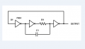
So is C1 connected to the input of gate 2 and if so do I add a 2nd connection that ties gate 1 to gate 2 (plain wire)? Thats where I get lost.

then for gate 2 and 3: gate 2 output is connected to R1 and the other end of R1 goes to a point that carries both C1 and R1 as an input to gate 3? those changes of additional components and lines between the gates confuse the crap outta me. I will try and wire this up tonight, or early tomorrow morning and take a picture. of the whole thing. I have tried another 7404 chip just in case I got a crummy one. no difference. Also doesn't help I'm learning to how use the Oscilloscope, but I think that part wouldn't show me a messed up graph off the bat if it was configured correct. I hope...lol.
 

crutschow

Joined Mar 14, 2008
38,842
I ripped out all the cables except for pwr and grnd because I am still trying to figure out how to wire that picture on a breadboard. My brain just doesn't get it. I told you I'm a newb , like newb newb :(
Put the IC pin numbers on the circuit schematic.
That will help you wire the breadboard.
 

MrChips

Joined Oct 2, 2009
35,198
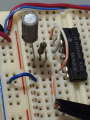
I moved the IC up so that the breadboard numbers match the IC pin numbers.
I changed C1 to 100nF so that you can have a better view of the breadboard wiring.

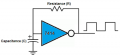
R1 = 1kΩ
C1 = 100nF
f = 4.8kHz

1679430931378.png

Oscilloscope View

1679430970715.png
 

Thread Starter

anglerfish27

Joined Mar 21, 2023
18
Amazing thank you guys, going to wire this up, and once I get an Oscilloscope output that doesn't look like a 4 year old went nuts with crayons I will post it, along with the BB layout. Can't thank you enough!! All of you! Sad to hear sounds like I wasted some money on 7414's lol. But there's always another project I find a use for them!
Cheers.
 

MrChips

Joined Oct 2, 2009
35,198
I ripped out all the cables except for pwr and grnd because I am still trying to figure out how to wire that picture on a breadboard. My brain just doesn't get it. I told you I'm a newb , like newb newb :(
When a circuit on a breadboard does not work, don't rip it appart and start over again. You don't learn anything by doing that.
Trouble shooting a circuit is one of the essential skills that you have to develop by yourself. You would never know what you did wrong in the first place if you start over.
 

WBahn

Joined Mar 31, 2012
33,234
Amazing thank you guys, going to wire this up, and once I get an Oscilloscope output that doesn't look like a 4 year old went nuts with crayons I will post it, along with the BB layout. Can't thank you enough!! All of you! Sad to hear sounds like I wasted some money on 7414's lol. But there's always another project I find a use for them!
Cheers.
7414's (if the right family) are useful for all kinds of things. I always wished I had more of them lying around.
 

Thread Starter

anglerfish27

Joined Mar 21, 2023
18
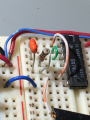
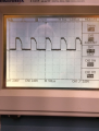
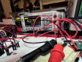
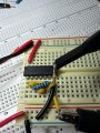
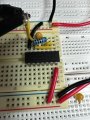
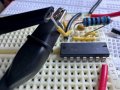
Hey team, I did some testing yesterday. Fresh bread board, custom cut wires, brand new cap and resister tested for tolerances, wired it up exactly as in the picture. I could not reproduce the waveform on the oscilloscope that MrChips has. Granted I'm still learning the damn thing 300 page manual and a demo board with instructions that are useless for a beginner, I bought a book to try and help. (I have dozens of books on all kinds of subjects.)

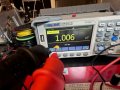
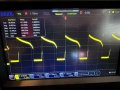
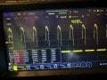
I'm guessing not being able to reproduce the nice waveform has to do with user error on the oscilloscope. Though it and my DMM both gave me a frequency of about 4.13KHz (not 4.8KHz) not sure if that is in the range of tolerance. Then I tried again this morning using an aluminum cap instead of a ceramic one, the waveform changed again and I was unable to get anything remotely like a true (or close to) a square wave. Still averaging around 4.13KHZ with a max hitting 5KHz. I sat there and played with the oscilloscope for hours. I did notice that my peak-to-peak values matched MrChips' values on the oscilloscope. So I guess that's a start. Dont know what I'm doing wrong. For the record, I did not just rip out the wires the first time it didn't work :) I traced everything over and over with pen and paper, using the DMM to test for voltage and currents. For whatever reason, I simply could not reproduce the circuit from the book. I spent roughly 30 hours between 2.5 days trying to figure this out (which I don't think anyone here has done and succeeded? So. At several points, I was ok like let me start fresh. I don't give up easily and it's eating me up at this moment I do not know what I'm doing wrong, or if its something stupid with the Oscilloscope or if I have some weird batch of 7404's, I even ordered "vintage" 7404's the exactly that MrChips used and another one from Motorola. In hope that'll do the trick.

While yes I need this as I'm essentially building a logic test board the kinda that are like $1K. Its driving me insane I can' even wire up the original circuit from the original post. I would love to see someone do that and if it does gives 1KHz. I tried putting a decoupling capacitor in parallel(.1uf and 10uf) this morning to see if that helps at VCC, nope that made it worse on the oscilloscope, basically was giving me a flat line. See attached pictures/filenames.
Still feeling defeated :(
 

Attachments

Thread Starter

anglerfish27

Joined Mar 21, 2023
18
Oh, I forgot to add, on the oscilloscope I tried using a square wave, a square pulse, and a slope. For the measurement modes. It's a Rigol 5104 4-channel. I have tried the digital logic portion of it to see if that made any difference, that flat-out didn't work (likely user error). I am going to try after work with my Salae Logic Pro LA, one I understand better how to use and have used for things such as I2C communication troubleshooting on some of my Raspberry Pico projects. Help me verify my code creating custom drivers for the sensor to make sure was working as expected (or at least getting the values I was sending in C).
 

Audioguru again

Joined Oct 21, 2019
6,826
I have never seen old-fashioned 74xx TTL outputs on an oscilloscope. I knew their output high might be as low as 2.4V but I wrongly thought the waveform would be fairly good squarewaves that are flat on top.
 

Thread Starter

anglerfish27

Joined Mar 21, 2023
18
Yeah, the pictures are AUTO and one is a pulse train square wave (that's what I'm calling it it's not called that) and slope.

Mr. Chips. was able to get fairly good waveforms but I am unsure if he manipulated it (the oscilloscope).

In other news besides still trying to figure this out (has ANYONE been able to make 1KHz the way the book has laid on in its schematic?

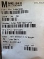
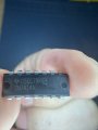
Also, I got in the mail today some 7414 labeled as Hex Schmitt-trigger inverters
SN7414N (MFG part #).

How would the circuit change use one of these? I also got but I really do not want to use them for this as this is something a 7404 chip should be able to pull off, a 1MHz a 10MHz, and a 1KHz crystal that is breadboard friendly. I feel that's "cheating" and rather save them for something else but if you have a working diagram schematic (or Bread board pic is even better) of how to do that with either the 7404N or the 7414N please share :). Thank you all and your brilliant minds for having patience with me. :)

Cheers.
 

Attachments

sarahMCML

Joined May 11, 2019
703
I have never seen old-fashioned 74xx TTL outputs on an oscilloscope. I knew their output high might be as low as 2.4V but I wrongly thought the waveform would be fairly good squarewaves that are flat on top.
I just tried post #27 with an old 7404 and got the same waveform, but found that the poor falling edge is an artifact of the circuit. I removed the capacitor and input squarewaves from a pulse generator, then scoped the output of the first and second inverter. The pulses were nice 3.8V flat topped pulses with rise and fall times of ~5ns.
 
Top