Newbie - Using a 7404 NOT Hex Inverter to get a frequency wave 1Khz.

Audioguru again

Joined Oct 21, 2019
6,826
The original circuit in post #1 had a 150 ohms resistor that has resistance too low.
The actual IC used was not a powerful 7404 but instead it was a weaker 74LS04.
 

sarahMCML

Joined May 11, 2019
703
Correction: The circuit I could not get to oscillate was the original one as shown in Post #1 and #4.
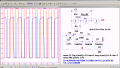
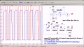
I tried the circuit in post #1 with my chip (Signetics 1977 7404) from post #38, using an old 20% C280 22nF capacitor and 150 Ohm resistor, and it produced a 112KHz 4 volt square wave just like Bordodynov's.
 

Thread Starter

anglerfish27

Joined Mar 21, 2023
18
Well, I figured out at least part of what I did wrong. I was getting the same results with a 7414N. I used the schematic posted above and even found a youtube video of some guy wiring up an LED. In my epic failure, I found out I was actually using a capacitor that was not the right size (by a lot). So I went to a cheapo aluminum can cap rated at 1500uF and a 150Ohm resistor (from the original post book values trying to get 1Hz. Well. I managed to get a square wave but it clocked in at 3.6 - 4Hz no matter what messing around I do on the scope. I did notice playing with the amount of current on the benchtop made a difference in getting the wave "square" or mostly square. Seems like there was the perfect combo for the wave. However, I don't understand the rules of electronics in this situation. There's a min and max current that will give me a square or a square with a bend on the top, after those thresholds the square wave doesn't change no matter how much higher you go in current, and if you too low you flatline.

The youtube video the guy said he was setting his PSU to 5V and "no current limit" he didn't show it on camera, and I don't think my PSU works that way in terms of "no limit"

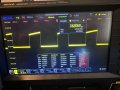
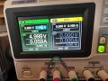
See the attached images of the waves and the voltage/current combo used to create them.

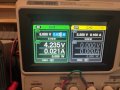
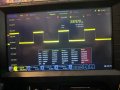
image 0 and 1 are the sweet spot so to speak, the closest to 5V out with a nice wave, I'm guessing the OUT values on my PSU are high enough for a digital high/low per the 7414N. (PSU set 5V and current is 22mA. OUT is 4.2V (this fluctuates .1-.3V) about and 21mA) Freq = 3.9Hz

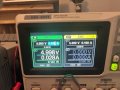
Image 2 and 3 show too much current hence the hump on the top, if you continue to raise the current nothing happens in terms of change. This gets me the closest to OUT being 5V. Current set to 32mA but at cost of the wave deforming a bit. Freq = 3.6Hz

Image 4 and 6 and 7 (not sure why there is not a image 5..) set to 5V and 26mA gives us 4.9V OUT with a mostly decent square wave. Freq = 4.09

I dont see a correlation really here. Frequency always fluctuates on any of the settings. Per the schematic this should be 1Hz not high 3 almost 4Hz, the resistor is 1% tolerance, and the cap is likely 20% could that do it? I'm going to clean it up as I put this one together in haste. Making sure everything is grounded well, with custom-cut wires and a decoupling cap all inputs go to the ground right now, which is tied to my negative "black" terminal on my PSU. I heard from many that's kind of the standard way to set it up.

Open to suggestions about currents, what should I be using? Components, any type of cap is better than another. I'm going to order some up with very tight tolerances.

What about IC's should I be looking at the "HC" versions? instead of just the chip number or LSxx?

Glad I got this sorta working I would call the expected 1Hz and got 4Hz a success but at least I'm getting a square wave, also, I've noticed that my values are in mA's whereas other's Oscilloscopes show 0 to 5V for the square wave, I have an odd mA number. It's set to volts on the output. Confused.
 

Attachments

MrChips

Joined Oct 2, 2009
35,033
Here are some tips.

1) Don't mess around with the current limit from the power supply.
Set the power supply to the voltage specified in the device data sheet. All SN7400 series and SN74LS00 series IC require 5.0V power.

2) If you get droop on the top or bottom of the trace consider that to be normal. To square it off, send the signal through another 7414 gate.

3) Ignore tolerances. All devices will have some uncertainty. Instead, use a trimmer resistor to dial in the frequency you want.

4) If you want exactly 1Hz or close to 1Hz, it might be difficult trimming the resistor value to get close to your desired frequency, especially when using large value electrolytic capacitors. It would be better to go to a higher frequency and then scale it down with a divide-by-N counter. Check out CD4020, CD4040, and CD4060 ICs.

5) If you are looking for stable and reasonably accurate 1Hz and 1000Hz clock then you should be using a quartz crystal oscillator.
 

WBahn

Joined Mar 31, 2012
33,081
Sounds like you are confusing current and voltage.

For most circuits (and that most definitely includes this circuit), you set the power supply to a certain voltage and you let the circuit pull whatever current it needs to at that voltage. As long as the power supply can actually supply that much current, life is good. Most power supplies that people use don't have any current limit beyond the natural limitation that there is simply some maximum current that the supply can deliver. If you do have a current limit adjustment on your supply, you want to set it high enough so that it never kicks in. Most of the time, you just turn it all the way up.

As you adjust the voltage, you will go from a low level where nothing works, to a level where things start working pretty quickly. Then, as you take the voltage higher, you should only see a pretty minor change in the behavior (the output voltage will increase, but the frequency will only change a little bit). If you continue going higher you will reach a point where things fail, very possibly catastrophically, either by letting the magic smoke out, or just damaging the parts so that they will never work properly again.

Changing your scope settings isn't going to change the frequency that the waveform is at -- it will just change how it appears on the scope. You don't WANT your scope settings to affect how the circuit behaves in any significant way.

There is going to be a lot of variation in the actual frequency that these kinds of oscillators run at. Part of this is component tolerance, but a bigger part is that these parts have poorly defined transition thresholds (they are, after all, meant to be used as digital parts). The actual frequency of oscillation is going to be pretty sensitive to the exact transition thresholds exhibited by each of the gates that is seeing a slowly changing input. While you can add a pot/rheostat (also referred to as a trimmer) to allow you to adjust the frequency to what you want, that frequency isn't going to be very stable and will change as things like the supply voltage or the temperature change.
 

Audioguru again

Joined Oct 21, 2019
6,826
A 1500uF metal can capacitor is electrolytic and is polarized with one wire positive and the other wire negative.
BUT the circuit needs a capacitor that is not polarized because both of its wires alternate positive and negative.
Your wrong type of capacitor affects your very old TTL circuit.
Non-polarized electrolytic capacitors are available at some places and are marked NP.

If you use a modern Cmos logic IC then you could use a 1M resistor and a 220nF (0.22uF) film capacitor.
 

Thread Starter

anglerfish27

Joined Mar 21, 2023
18
Thanks for the info, I really appreciate it as I stumble my way through this. Seriously THANK YOU!

So I don't think my benchtop PSU lets me just set 5V and not a current, there's a CV (constant voltage) and CC (constant current) indicator (but no way to set it to either). I noticed that the LED will change in color as you raise the current to the point "no more is needed" and then it stays on CV. Interestingly enough my 3 power input is just a slide switch 2V 3.3V or 5V if I set it to 5V (nowhere does it tell me anything that its actually pulling voltage or current), I get a pretty solid wave at some mystery current. See pics below. The PSU book is here if you are curious if you can set it to just CV and let pull however much current it needs up to the limit of the PSU which is 3.2A.

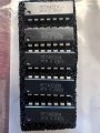
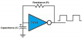
I have already ordered smaller capacitors multilayer ceramic or film I forget. The polarity thing for the cap didn't cross my mind, that makes sense, surprised I didn't let the magic smoke out, maybe because it's switching so fast? You say I'm using "old chips" so to be clear I should be using chips with "HC" or CDxxxx as the numbers. Here are a few old 7404s I picked up. I am curious since the book came up with this diagram and layout. See OP. Why they would put it that way if it's not optimal?

I tripled my resistor and I am getting very close to 1MHz now which is cool. This was more of I won't be beaten by this and I will figure it out!

I did purchase and now have 1MHz 10MHz and 100KHz crystals. How would I go about using them (schematic + breadboard would be gold) to get the crystals to give me accurate timing? I should use this in combination with the "newer" ICs, right? The HC or CD chips.

I also did purchase last night smaller non-polarised caps with low tolerances to replace the aluminum cap along with ultra-low .01% tolerance on a handful of resistors that per the calculator should give me these frequencies. I like the trimpot idea, brilliant, will order a good one. I have some but the tolerances on them are crappy.

I know stupid questions for you guys but you have taught me so much already by my trial and error and your explanations and help with the darn breadboard wiring. That always trips me up. Is there some software out there that would translate a schematic into a BB layout? Probably not.

So to wrap this up a few questions mentioned above summed up:
#1 I should buy and use HC or CD chips for the 74xx series to do projects such as these. This is a biggie I may need to order a bunch of new chips if the LS ones are not going to work right with all the digital logic labs it has in the book.

#2 Should I be using the analog portion of my scope to measure or the digital portion? (I assume analog)?

#3 Should I buy a new PSU one that will let me just set the voltage and let the DUT pull what it needs current-wise? If so recommendations I know I have a crappy one.

#4 How and what components should I use for the crystals with the same questions as #2?

#5 Do you normally use 1 cap or two in parallel for smoothing out power signals, what values do you tend to use?

#6 Are ferrite beads on the power and ground lines a good idea?

Thanks, everyone so so much, looking forward to your responses!!
 

Attachments

MrChips

Joined Oct 2, 2009
35,033
CC vs CV

This is a common confusion for newcomers to PSU (power supply unit).

CC (constant current) and CV (constant voltage) settings are maximum limits. You cannot invoke both at the same time because they are interdependent on the load resistance R.

Ohm's Law:
I = V/R
V = I x R

In most cases, you want to set the voltage limit, e.g. set the voltage to 5V. The you set the current to the maximum.

There are two cases when you might want to set the current limit. For example, if you want to protect a sensitive circuit whose expected operating current is 50mA, you might want to set the limit to 60mA.

In a second example, the device operates at a fixed current, e.g. 20mA, then you would set the current limit to 20mA. You would then increase the voltage setting from 0V to the point where then CC light turns on, then set the voltage slightly higher.

How do you set the current limit?
Set the CV control to midrange. Short the output of the PSU and dial the CC control until you get the desired CC limit.

In summary, the PSU is always operating in CV mode or CC mode, not both at the same time.
The PSU will be in CV mode or CC mode which ever limit is reached first.

I will answer your 6 questions in my next post.
 

WBahn

Joined Mar 31, 2012
33,081
So I don't think my benchtop PSU lets me just set 5V and not a current, there's a CV (constant voltage) and CC (constant current) indicator (but no way to set it to either). I noticed that the LED will change in color as you raise the current to the point "no more is needed" and then it stays on CV. Interestingly enough my 3 power input is just a slide switch 2V 3.3V or 5V if I set it to 5V (nowhere does it tell me anything that its actually pulling voltage or current), I get a pretty solid wave at some mystery current. See pics below. The PSU book is here if you are curious if you can set it to just CV and let pull however much current it needs up to the limit of the PSU which is 3.2A.
Nearly all limiting supplies work about the same way.

You essentially set both a voltage limit and a current limit. Which mode the supply actually runs in depends on the load -- it will switch back and forth between modes automatically.

So let's say that you set the voltage for 10 V and the current for 100 mA.

With nothing connected, the "constant current" side of the supply would want to increase the voltage to some huge voltage that would cause a 100 mA arc to appear between the terminals. But as soon as the voltage gets to 10 V, the supply switches to a constant-voltage mode and so the terminal voltage stays at 10 V with no current.

Now you connect a 1 kΩ load and current starts to flow. Since 10 V across 1 kΩ is only 10 mA, the supply stays in constant-voltage mode because of the 10 V limit that has been set.

Now let's say that you put eight more of these 1 kΩ resistors (in parallel) across the outputs of the supply. You are now drawing 90 mA, but the supply will still be in constant-voltage mode.

Now you start increasing the voltage limit setting on the supply. When you get to 11.1 V, the total current draw will be right about the 100 mA limit that is set. If you turn the voltage limit up to 15 V, the supply will switch over to a constant-current mode and not let the voltage go any higher than the 11.1 V because anything more would exceed the 100 mA limit.

If you now remove two of the resistors (leaving you with seven, which is therefore about 143 Ω), the supply output voltage will increase to 14.3 V, but it will remain in constant-current mode at 100 mA.

If you remove another resistor, leaving 167 Ω, the voltage will raise again, but it would need to rise to 16.7 V in order to remain in constant-current mode, so it will switch to constant-voltage mode once it hits the 15 V limit and the output current will drop to 90 mA.

In practice, if you want the supply to behave like a "normal" voltage supply, you simply turn the current limit up as far as it will go and set the voltage limit to the value you want. Similarly, if you want it to behave as a "normal" current supply, you turn the voltage up as far as it will go and set the current limit to the value you want.

A better approach, when you want a voltage supply with a "safe" current limit in place, is to set the voltage limit, with no load attached, to the desired output voltage. Then, short the outputs of the supply and adjust the current limit to the maximum current you want to deliver to your load. Now connect your load. The supply should remain in constant-voltage mode unless something goes wrong, in which case the current limit will kick in. You can do a similar approach when you want the supply to be in a constant-current mode with a "safe" voltage limit.

Another approach that can be useful in many situations, particularly testing/debugging situations, is to set the voltage limit for the desired voltage (with no load), then set the current limit to zero and attach your load. Now start turning up the current limit. As you go, the voltage will rise. If things are good, the voltage will go into voltage-limiting once you are allowing the current limit to rise above what the load needs at the desired voltage output. But if there's an issue and the device is going to pull too much current at the desired voltage, you will be able to see that start to happen as you gradually increase the current limit -- you will pass the point where the current should have stopped rising but the voltage is still way too low. The voltage at which this happens can often give useful clues about what is going wrong.
 

MrChips

Joined Oct 2, 2009
35,033
#1 I should buy and use HC or CD chips for the 74xx series to do projects such as these. This is a biggie I may need to order a bunch of new chips if the LS ones are not going to work right with all the digital logic labs it has in the book.
Buy and use whatever series fits your application and budget. Each family has different characteristics and they are used in different applications. Do not mix families unless you know that they are compatible.
For hobby use and experimenting, you should stick with one family to minimize stocking costs.

7400 - 5V, power hungry, not recommended for new designs
74LS - 5V, uses less power
74HC - 2-6V, very low power, compatible with CD4000
74HCT - 5V, very low power, compatible with 74LS00
CD4000 - wide operating voltage 3-18V, very low power, not compatible with 7400, 74LS00

If I were starting out and wanted to build a collection of digital ICs for present and future projects I would choose 4000 series ICs.

#2 Should I be using the analog portion of my scope to measure or the digital portion? (I assume analog)?
There is no such thing as analog vs digital portion of the oscilloscope. If you mean the DMM function of the oscilloscope, then that is not an oscilloscope. The primary function of the oscilloscope is to display the analog waveform of a signal. Modern DSO have the ability to display some information digitally while still showing the waveform.

#3 Should I buy a new PSU one that will let me just set the voltage and let the DUT pull what it needs current-wise? If so recommendations I know I have a crappy one.
This has been explained. There is nothing wrong with your PSU. For common digital circuit applications, set the voltage to 5V and set the current to maximum.
#4 How and what components should I use for the crystals with the same questions as #2?
This calls for a separate discussion. The simplest solution when a crystal controlled clock is required is to buy a crystal oscillator module. You apply 5V power and you get the specified output frequency,
#5 Do you normally use 1 cap or two in parallel for smoothing out power signals, what values do you tend to use?
The rule of thumb differs if you are breadboarding a circuit or you are building a PCB for production. It also depends on the circuit application, analog vs digital, and frequency of operation.

For a professional PCB for production, one 100nF ceramic capacitor goes across the power pins at every chip.
For analog application, one might add 10μF electrolytic capacitors across the power rail at sensitive circuits.

For the hobbyist building on a prototyping board, you might get away with no decoupling capacitors. If you run into trouble, add one 10-100μF electrolytic capacitor across the power rails.

(For power supply noise reasons, don't buy NE555 or LM555 timer ICs unless there is reason to use these. Buy CMOS versions such as LMC555, TLC555, ICM7555.)
#6 Are ferrite beads on the power and ground lines a good idea?

Depends. For hobby experiments you can ignore this.
 

sarahMCML

Joined May 11, 2019
703
Thanks for the info, I really appreciate it as I stumble my way through this. Seriously THANK YOU!

So I don't think my benchtop PSU lets me just set 5V and not a current, there's a CV (constant voltage) and CC (constant current) indicator (but no way to set it to either). I noticed that the LED will change in color as you raise the current to the point "no more is needed" and then it stays on CV. Interestingly enough my 3 power input is just a slide switch 2V 3.3V or 5V if I set it to 5V (nowhere does it tell me anything that its actually pulling voltage or current), I get a pretty solid wave at some mystery current. See pics below. The PSU book is here if you are curious if you can set it to just CV and let pull however much current it needs up to the limit of the PSU which is 3.2A.

I have already ordered smaller capacitors multilayer ceramic or film I forget. The polarity thing for the cap didn't cross my mind, that makes sense, surprised I didn't let the magic smoke out, maybe because it's switching so fast? You say I'm using "old chips" so to be clear I should be using chips with "HC" or CDxxxx as the numbers. Here are a few old 7404s I picked up. I am curious since the book came up with this diagram and layout. See OP. Why they would put it that way if it's not optimal?

I tripled my resistor and I am getting very close to 1MHz now which is cool. This was more of I won't be beaten by this and I will figure it out!

I did purchase and now have 1MHz 10MHz and 100KHz crystals. How would I go about using them (schematic + breadboard would be gold) to get the crystals to give me accurate timing? I should use this in combination with the "newer" ICs, right? The HC or CD chips.

I also did purchase last night smaller non-polarised caps with low tolerances to replace the aluminum cap along with ultra-low .01% tolerance on a handful of resistors that per the calculator should give me these frequencies. I like the trimpot idea, brilliant, will order a good one. I have some but the tolerances on them are crappy.

I know stupid questions for you guys but you have taught me so much already by my trial and error and your explanations and help with the darn breadboard wiring. That always trips me up. Is there some software out there that would translate a schematic into a BB layout? Probably not.

So to wrap this up a few questions mentioned above summed up:
#1 I should buy and use HC or CD chips for the 74xx series to do projects such as these. This is a biggie I may need to order a bunch of new chips if the LS ones are not going to work right with all the digital logic labs it has in the book.

#2 Should I be using the analog portion of my scope to measure or the digital portion? (I assume analog)?

#3 Should I buy a new PSU one that will let me just set the voltage and let the DUT pull what it needs current-wise? If so recommendations I know I have a crappy one.

#4 How and what components should I use for the crystals with the same questions as #2?

#5 Do you normally use 1 cap or two in parallel for smoothing out power signals, what values do you tend to use?

#6 Are ferrite beads on the power and ground lines a good idea?

Thanks, everyone so so much, looking forward to your responses!!
The Power supply that you have is most definitely NOT a crappy one, quite the reverse in fact, I wish it were mine! Your problem is not yet understanding the Constant Current setting function.
Its usual purpose is to protect the circuit being powered from harm if there is an unknown fault during test. For example, when designing a circuit it's normal to have some idea of the maximum total current that it should take if operating properly.
So the designer will, before powering up, set the Constant Current setting of the supply to say, 10% above that value. This is to allow for any component tolerances, etc. The Voltage will have been set to the designed value for the circuit.
If, in the case that there is a short circuit or a bad component, and the whole device takes too much power from the supply, the Constant Current limit will come into play, and the output voltage will drop, limiting any damage to the device.

There are instances where the power supply is used as a Constant Current source, but they are much rarer.

1) I'd steer clear of the old 74xx and 74LS and concentrate on 'HC and HCT series logic chips for their lower power consumption. The CD series are slower, but great if you need higher than 5V working, although some special function CD chips do have 74HC/T equivalents, such as the 74HC4017.
If you already have 74LS chip, use them. I have lots, and still use them up.

2) The analog side of your scope is useful for everything, the digital side only for digital!

3) see above!

4) Do you actually have those MC74HCU04's? They are un-buffered versions of the 74HC04 inverters, and are ideal for making linear amplifiers (of a kind!) You could probably get one of those, together with a crystal and a couple of small capacitors and resistors to oscillate. I'd think the 100KHz and 1MHz would be OK, but the 10MHz might struggle. I'd draw something up, but I must go soon. Look Up
Using CMOS Schmitt trigger inverters in quartz crystal oscillator circuit


5) A 0.1uF together with an electrolytic every so often works for me.

6) Never used any.
 

WBahn

Joined Mar 31, 2012
33,081
I am curious since the book came up with this diagram and layout. See OP. Why they would put it that way if it's not optimal?
There's no definitive answer for this, but one thing that you'll discover is that the people that write books often have little, if any, "real world" experience. It's possible that the person that wrote it never even attempted to build it. I have no idea if that's the case here or not.

Also, a lot of diagrams are only intended to be conceptual in order to communicate something about a circuit or approach and not really intended to be fully fleshed-out designs. These will often just indicate the logic function (e.g., 7404 to indicate that it's an inverter) and not the family. In many designs, the family isn't important as long as all of the chips used are compatible with each other. But in some circuits, it matters a great deal. This is one of them.

#1 I should buy and use HC or CD chips for the 74xx series to do projects such as these. This is a biggie I may need to order a bunch of new chips if the LS ones are not going to work right with all the digital logic labs it has in the book.
Unfortunately, "projects such as these" is pretty ill-defined. Which family to use depends on a number of factors, mostly regarding what other circuits will the logic chips be interfaced to. Each family (and there are many others) was designed to fill a need.

My go-to family is the 74HC family. But this is because I started learning this stuff using 74xx parts conceptually, and so those are more familiar to me. I seldom need something that the 74HC family won't work for, so that's what I tend to stick with.

#2 Should I be using the analog portion of my scope to measure or the digital portion? (I assume analog)?
Each has features that the other lacks. In general, use the analog side for analog signals and the digital side for digital signals. Be sure to know what kinds of digital signals the digital side can work with. It likely has settings for you to either pick different logic families or to manually adjust HI/LO thresholds.

#3 Should I buy a new PSU one that will let me just set the voltage and let the DUT pull what it needs current-wise? If so recommendations I know I have a crappy one.
That is NOT a crappy supply! It would be a significant upgrade from anything I have, that's for sure. You just need to learn how to use it, which comes with practice and study.

#4 How and what components should I use for the crystals with the same questions as #2?
Pretty much the same answer as #2. Beyond some level, all digital circuits are analog circuits. Depending on what you are trying to examine, you can use either side of the scope. Be aware that crystal oscillator circuits (in fact, most oscillator circuits) are pretty sensitive to parasitic effects on certain nodes, so just connecting a scope probe has the potential to change the circuit's behavior. That can be quite frustrating, but with experience you will get a feel for how to tell where you can and can't probe.

#5 Do you normally use 1 cap or two in parallel for smoothing out power signals, what values do you tend to use?
It depends on the particulars of the circuit, but a good rule of thumb is to put 100 nF caps as close as possible to the power pins of each IC. For higher speed signals, I often also put a 10 nF cap in parallel with it. An occasional larger cap, such as a 10 uF to 100 uF electrolytic, is good, particularly if you have long traces or cables separating the power source from the components. I call these "power-entry" or "entry-point" caps. I sometimes also place them at the far end of the circuit as far away from the power entry point as possible. On a large circuit board, particularly if I have higher-speed signals running around, I will place 1 uF to 10 uF "bulk storage" caps at a ratio of about one cap per five to ten ICs.

This is a strategy that is often referred to as "decade-tiering" because device parasitics place an upper limit on the frequency at which a capacitor actually behaves like a capacitor and, in general, the larger the capacitance, the lower the frequency where that happens. The idea is for the larger caps to be reservoirs of charge to feed the smaller caps while the smaller caps deal with the high-frequency noise at a very local level.

But the specifics of whether this is good enough, overkill, or just-getting-started depends on the nature of the circuitry, the kinds of signals being used, the kinds of interfering signals that are around, and how sensitive different parts of the circuit are to noise.

#6 Are ferrite beads on the power and ground lines a good idea?
You probably will never need them. For circuits that you are breadboading, they will almost certainly not do any good -- too many ways for the circuit to pick up the noise other than the power/ground lines.

For the things that I have done, they have been very handy in keeping high speeds signals where they belong and not letting them sneak out from one part of the circuit (such as a digital section) and become power-supply noise in another part (such as a sensitive analog section). But if you have a circuit where they are needed, they are almost always just one component of a much larger strategy that is needed to get the circuit to behave as desired.
 

Thread Starter

anglerfish27

Joined Mar 21, 2023
18
Thank you so much for the information!! I placed an order for a mix of HC and CD chips of various kinds as this is part of a series of books I found that show you how to use IC's to make all kinds of things (Forest Mimms book) flip flops, memory, latches, timers, amplifiers, multiplexers etc... you name it. However before I could start building those circuits I needed either #1 buy a professionally made analog logic test board ($500-$1k) OR it gave me the schematic on how to make my own, the part I was struggling with was the OP for the two frequency wave generators. I know there are easier ways with other chips to pull this off and with crystals. The 100KHz crystal through hole is tiny I have no idea how to even get that to fit!

I've got the 1HZ signal and I'm waiting on the parts (probably today) to make the 1KHz signal and the 1MHz signal again not using an aluminum cap but instead a cap that does care about polarity. Then I'm all set to start building some of the circuits. Thank you for all of your help. I'll be back once I stumble into something else I can't figure out. I don't post unless I've exhausted my own ability to try and solve it. :)

Cheers
 
Top