 Facebook
 Google
 GitHub
 Linkedin
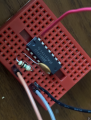
Hi, I'm trying to make an simple oscillator with cd40105 chip and 9v battery.
I'm using a 0.1uf capacitor and one 10k ohm resister, but It doesn't make any sound.
I tried with the 100k ohm, but still doesn't work.
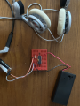
When I turned on the battery, It first sounded like a lower beep, but very few times after it didn't make a sound anymore. What should I do to make proper sound?
I'm referencing this video -> https://bastl-instruments.com/support/tutorials/omsynth-project-1
I'm using a 0.1uf capacitor and one 10k ohm resister, but It doesn't make any sound.
I tried with the 100k ohm, but still doesn't work.
When I turned on the battery, It first sounded like a lower beep, but very few times after it didn't make a sound anymore. What should I do to make proper sound?
I'm referencing this video -> https://bastl-instruments.com/support/tutorials/omsynth-project-1
Attachments
-
 2.8 MB Views: 21
 -
 3 MB Views: 21


