Your capacitors look like ceramic type. Maybe their value is plus or minus 20 percent or worse. You should use 5 percent metalized plastic film type of capacitors then the frequencies will be more accurate.
Your capacitors look like ceramic type. Maybe their value is plus or minus 20 percent or worse. You should use 5 percent metalized plastic film type of capacitors then the frequencies will be more accurate.
EDIT: I bought a metallized polyester film capacitor 2.2 nf. It says +/-5% too so I figure it'd work. Thanks
Thanks. I found "stacked metallized plastic film" under poly film capacitors on digi-key: http://search.digikey.com/scripts/D...rds=metallized+plastic+film+capacitor&x=0&y=0
is this the same thing? They don't have 2.2 nF (your recommendation so I can use 10K resistor which per your comments in minimum with 5V to CD4093, I still haven't figured out how one gets this from the spec...), so I'd have to get at least 10 nF, not sure this would work. Maybe there's another place to get them that's good? Google didn't come up with anything that looked useful...
Don't know if this is different, but they seem to have those in 2.2 nF. It seems the _stacked plastic_ is the one that doesn't come that low, at least at Digi-Key...
Now from my understanding of the virtual wall the 35 kHz carrier is critical, and I believe this should be the pin 10/11 value per my understanding of the circuit. I am also thinking I will need to increase the resistance of the 10K resistor to get 35 kHz vs 107.7 kHz, and per my calculations this would have to be approximately 30K (30571, probably doesn't exist like that exactly). I am guessing I would need a 30K potentiometer resistor. I already have a 20K so maybe I'll try that to see if my theory is right and if the frequency goes down to 53.5 kHz with the 20K at max...
Any thoughts on my ideas?
Thanks
Misha
p.s. Audioguru, could you tell me how you figured out that the smallest resistor the CD4093 can support at 5V is 10K? I just can't figure this out from the spec for the life of me... It would be helpful and great to learn this. Thanks
p.p.s. It seems like then I could increase my capacitor capacitance and use my 20k potentiometer as well...
Thanks a lot. Btw, I am confused about the part of the circuit where the outputs from the first two Schmitt trigger NAND gates that are used for oscillation are fed back into the third Schmitt trigger, and then that output is fed out into the fourth again. What are these for? How does one compute the frequencies seen on 10 or 11? I understand how to get 3 & 4 and the relationship of those with the R & C values, but I don't understand what is going on on 10 or 11.
My guess was that these combine 3 & 4, but this is clearly not the case in any simple way based on my measurements (e.g., just modulate 3 on top of 4, which should still be close to 4, not so different).
IC1B is the high frequency oscillator and IC1A is the low frequency one. The low frequency gates the high frequencies on and off in the logic gate IC1C. The output of IC1C is high when the oscillators are off and could drive a PNP transistor that drives the LED but instead, IC1D is added as an inverter so that an NPN transistor is used to drive the LED.
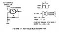
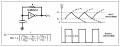
The datasheet for the CD4093 has the Schmitt-trigger threshold voltages. Here is a circuit with a formula to calculate the parts and the frequency.
IC1B is the high frequency oscillator and IC1A is the low frequency one. The low frequency gates the high frequencies on and off in the logic gate IC1C. The output of IC1C is high when the oscillators are off and could drive a PNP transistor that drives the LED but instead, IC1D is added as an inverter so that an NPN transistor is used to drive the LED.
The datasheet for the CD4093 has the Schmitt-trigger threshold voltages. Here is a circuit with a formula to calculate the parts and the frequency.
Thanks. So I hooked up a 10K trimmer instead of the 10K resistor and got the high frequency to be 35 kHz and the low to be around 430 Hz. I need to be modulating 500 Hz on 35 kHz, but apparently the 500 is not critical and the 35 kHz is. Now does this mean I am done frequency-wise, or does it matter that IC1C and IC1D still read >100 kHz? I guess I am just confused how the IC1C and IC1D outputs are calculated. I am pretty set on the IC1A and IC1B.

 Facebook
 Google
 GitHub
 Linkedin