Newbie needs help (LED "Flashbang" project)

Status
Not open for further replies.

Bernard

Joined Aug 7, 2008
5,784
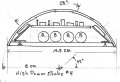
I would mock up output ckt first, LEDs, 5- 4 ohm 1/2W Rs, 10,000 uF worth of C's & 4 batteries. Charge up Cs, disconnect battery, dump Cs into paralled LEDs & Rs to see if brightness is as desired.
Buy a solderless breadboard to test out timing & flashing.
Had a few 2200 uF @ 16 V caps, only 22.2 mm long, 12.2 mm dia.
Except where noted all R's 1/4 W.
Think I would modify GopherT ckt. input to trigger on power-up.
How are you fixed for measuring instruments?
It's a start, open for review.
 

Thread Starter

Deus

Joined Jul 29, 2015
14
I´m sorry but that is way out of my league.

I have just started tinkering with electronics and tbh what you just wrote could just as well be rocket science to me ;)

I appreciate all your help and inputs (very much so!) but I need a "dumbed down version" of what you just wrote haha
 

Bernard

Joined Aug 7, 2008
5,784
Can you buy some electronic parts locally?
Buy a solderless breadboard, about 17 cm by 6 cm with 4 power strips, 2 on top, 2 on bottom.
Do you have a soldering iron?
Might be well to buy an electronic kit, one with a 555 & blinking LED's to practice on.
Do you have a battery box for 4 cells? Keep looking for suitable project container.
 

Bernard

Joined Aug 7, 2008
5,784
Another thought: A truncated clear plastic hemisphere would make a nice container, near edge almost at 45 deg., no light blockage from a top maybe negating need for 5th LED, could be made at home. Made one 6 in dia., slightly overheated causing bubbles in plastic
 

Bernard

Joined Aug 7, 2008
5,784
Butchered GopherT's ckt. a bit so all looked the same. C values can change to match available parts as long as R X C remain the same or as desired. Just a sketch as to what it might look like under the dome. There is about 3 X 3 in space for ckt. board. 2200 uF caps on other side of batteries. As LED light pattern overlap on top, see no need for 5th LED.HIGH PWR STROBE 2 00000.jpg HIGH PWR STROBE 3 00000.jpg
 

Attachments

Bernard

Joined Aug 7, 2008
5,784
'used a pot. for R8 to sample different flash periods, & as GopherT said in post #11, a short pulse might be more effective than long, so settled on 10 ms. on as best, 140ms. off, with R8 = 9.1k & R7 = 180k. Note as shown R7 & R8 are interchanged, my goof. Capacity can vary quite a bit from marked value of capacitors, so adjust R's accordingly.
Bread board looks good, at power up, 6 sec delay then 30 sec of strobing, then LEDs off.
I forgot to mention the need for jumper wires for solderless breadboard. I use 1/2 mm insulated solid telephone wire, 5mm stripped from each end.
 
Last edited:

ian field

Joined Oct 27, 2012
6,536
Hello all :)

Peter from Denmark here (so excuse any spelling blunders!)

I have just started fiddling with different kinds of electronics, most have to do with my hobby (Larping). I am going to a Firefly LARP (as a alliance police officer) in 4 months time and for that I require different kinds of equipment.

I can handle most of it but one of my (insane) ideas are a bit out of my league I´m affraid...

An "LED Flashbang".

And before any1 gets starter ;) Its a gimmick, a toy and I have NO intention of creating ANYTHING that could hurt or otherwise injure people!

My idea so far is to use some High lumen LEDs (I am thinking 750+ lumen per LED), wired to a 555timer, something that gives a Strobe effect, an automatic shut-off thingymajigger (that shuts off the lights after lets say 30 secs?), batteries and an On switch - All incased in some form of see through casing (think hamsterball).

Unfortunatly I do not have the knowledge to build it - granted I would just wired something up and pray to god that it works... But TBH I would really like to make something that works :)

So if any1 of you could spare the time to help me plot out a schematic and/or write a list of the components or just give general advice? I would appreciate it Very much! :D

The following is my brainstorm component list:

# LEDs - I have listed a few different kinds as I have NO idea which one will get the job done (or even works with a Strobe mode?)

220 Lumen LED: http://eud.dx.com/product/youokligh...m-24-smd-1206-12v-4pcs-844382062#.Vbidj_ntlBc

These are Cheap, small and easy to wire - But are they good enough?!

400 Lumen LED: http://eud.dx.com/product/t10-5w-40...rner-lamp-dc-12v-2-pcs-844252097#.Vbie5PntlBc

Almost the same as above - A bit higher lumen but will there be a big enough difference in the light output?

750 Lumen LED: http://eud.dx.com/product/t10-10w-7...rner-lamp-dc-12v-2-pcs-844255612#.VbifQ_ntlBc

Now we´re talking! High lumen still pretty cheap.

I have chosen the above as they are non-directional and 4~~ should be able to cast light in every direction in either a ball or a tube casing. But do they work? Can I wire them up to give a Strobe effect, ect?

# Timer - I have read that a 555timer should do the trick(?) I want the LEDs to start flashing (strobing? o_O) 6~10 secs after I push the "on button". Will that be possible with the 555?

# Strobe effect - Without the Strobe effect I would just be creating a pretty glowing ball - which is cool no doubt! But I want it to Strobe like there is NO tomorrow! Think Cree flashlight Strobe mode! I have NO idea how to do this? Please help :)

# Automatic shut off thingymajigger - I want the LEDs to automaticly shut off after around 30 secs after they start flashing. What can make it do this?

# Batteries - I haven´t really thought about these yet... Seeing as it depends on the components, ect.

# Casing - I am not set on the "hamster ball" casing seeing as perhaps a tube is easier to get a hold off. Any ideas would be appreciated!

If you made it this far I would like to say thank you and I really hope that you can either help me with the project or point me in the right direction ;)

Best regards
Peter
If you build a blocking oscillator/inverter to charge a capacitor up to about 40V or so, a DB3 diac breaks down at about 32 - 34V. That can be used to dump the capacitor charge into a parallel bank of LEDs every time it reaches the diac breakover voltage.

A good starting point is a 47uF electrolytic and the remains of a 24 LED magnetic work lamp.
 

Bernard

Joined Aug 7, 2008
5,784
Deus, I see that you peek in occasionally so still interested. The reason for suggesting a 555 timer kit is how close it is to your times & delays.
To see pictures of solderless & solderable breadboards go to All Electronics web site & look at CAT#'s PB-400, PB-840, JFF-200, SB-400, SB-800. on SB-800 there would be enough board left over for another project.
Any luck with securing some parts?
 

Thread Starter

Deus

Joined Jul 29, 2015
14
Hello all and sorry for the silence - I have been on vacation with the family ;)

In the interval GopherT has been so kind as to make a very nice schematic for the flashbang and I have already ordered most of the items needed.

Flashbang schematic.jpg

I have bought everything except all the small parts - My local DIY shop is having a hard time figuring out all the parts and he keeps saying that the schematic is incomplete?
 

Thread Starter

Deus

Joined Jul 29, 2015
14
As stated earlier I am a complete newb to this and although I can put the "puzzle together" I have no idea how the different parts interact with each other :) GopherT put the above schematic together and has been very helpful! :D
 

DerStrom8

Joined Feb 20, 2011
2,390
I have bought everything except all the small parts - My local DIY shop is having a hard time figuring out all the parts and he keeps saying that the schematic is incomplete?
I expect that is because you are missing part numbers (the 555 timers, the FETs, etc).

Only using one n type mosfet can do the job, you just in parallel with the resistors and leds.
This would require that the one FET be able to switch a high amount of current (several amps). Using separate FETs, each individual one doesn't need to have high current ratings. Sure it's possible to just use one, but it may not be the best option, depending on which LEDs the OP selects.
 

Bernard

Joined Aug 7, 2008
5,784
Some FET choices in desending order of preference, IRF520, IRF521, IRF522, IRF630, IRF523.
IRF520, 100V, 8A, .3 ohm. The list goes on & on- BUZ71A, 60V, 12A, .1 ohm; STP80NF12, 120V,80A, .013 ohm.
For PNP transistor- 2N3906. Resistors- 1/4 W , power switch & pushbutton SW. Large C, ( 10,000 ) for battery current boost.
Did you find a solderless breadboard, lot easier to make changes before commiting to hard wiring.
 

ian field

Joined Oct 27, 2012
6,536
Some FET choices in desending order of preference, IRF520, IRF521, IRF522, IRF630, IRF523.
IRF520, 100V, 8A, .3 ohm. The list goes on & on- BUZ71A, 60V, 12A, .1 ohm; STP80NF12, 120V,80A, .013 ohm.
For PNP transistor- 2N3906. Resistors- 1/4 W , power switch & pushbutton SW. Large C, ( 10,000 ) for battery current boost.
Did you find a solderless breadboard, lot easier to make changes before commiting to hard wiring.
With multiple MOSFETS as drawn, the BS170 at 500mA would be OK - those LED units are just a smidge over the 200mA rating of a 2N7000.

When I clicked the link in the OP by the TS, it opened a page of LED replacement bulbs for car dashboard crimp seal bulbs - they should be rated for 12V and already have whatever series resistors they need integrated in the assembly.
 

Bernard

Joined Aug 7, 2008
5,784
The last mention of LED's that I saw was a 10W, 11V @ 900mA, LED. I'm still going for the single FET LED driver with 4 LED's.
Also could drop PNP by interchanging 10K & 100K & paralleling 100k with diode, anode to pin 7- post # 30.
 

ScottWang

Joined Aug 23, 2012
7,397
This would require that the one FET be able to switch a high amount of current (several amps). Using separate FETs, each individual one doesn't need to have high current ratings. Sure it's possible to just use one, but it may not be the best option, depending on which LEDs the OP selects.
Yes, sometimes depends on the will of TS, sometimes depends how the parts TS can get, sometimes is for the price, maybe two pcs is cheap than one, sometimes using two parts is better than one, specially when considering the power consumption.

What I concerned was that when the better parts we can get, using one is better than two or more.

IRF4110PbF_Nch_100V120A_Vgs10V_4.5mΩ.pdf
IRF2805_Nch_55V75A_Vgs10V_4.7mΩ.pdf
IRFP2907_Nch_75V209A470W_4.5mΩ.pdf
STH260N6F6-2_Nch_60V180A300W_2.4mΩ_Vgs10V.pdf
FDP8440_Nch_40V80A306W_Vgs4.5V_2.4mΩ.pdf
 
Status
Not open for further replies.
Top