Facebook
 Google
 GitHub
 Linkedin
Hello. I was hoping someone could help me diagnose and fix a little PCB inside a collectible bottle that lights up with four Christmas tree lights. (If it wasn't for the outrageous eBay prices, I would just buy another.)
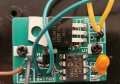
Photo #1 shows the internal wiring. From what I've gathered using my multimeter, the lighting (when operating correctly) worked like this: The power comes from three AAA batteries inside a battery holder attached to the PCB. The circuit to the lights is actually complete when the silver button attached to two green wires is NOT pressed. However, if I press & release the button, this interrupts the circuit, which then somehow causes the four Christmas tree lights to power on for 30 seconds. If I were to change the batteries, this would also cause an interruption of the circuit and, likewise, the lights would power on for 30 seconds.

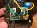
Photo #2 shows the underside of the PCB. There are two transistors and four resistors. Half are used for the positive line to the lights, and the other half for the negative line returning to the battery pack. The negative transistor is marked 58050 D.016 and there are no markings on the positive transistor.

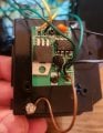
Photo #3 is my best attempt to explain how the electricity flows. (My apologies as I'm not very knowledgeable to draw up a professional-looking schematic.) From what I've discovered, the positive flow (depicted in red) starts off with 4.5v from where the batteries' positive line connects to the PCB and branches off in two paths. Likewise, negative (depicted in black) is returned to the batteries from two separate paths as well. I've noted the voltage in other spots on the PCB as it sometimes changes. Curiously, I measure 0 volts in the bottom right corner. Not sure if this is working as designed, but it remains 0 volts after I press the button now to test. Also worth noting, I drew a green line in the bottom right corner between two solder points. When I physically connect these two with metal, the bulbs light up. (But they only stay on as long as the connection is maintained. There is no "30 second timer" by doing this, and since I'd have to physically press the silver button to break the connection, this method will quickly drain the batteries.)

So due to my limited electronic knowledge I have three questions:
1. How does this board with two transistors and four resistors somehow simulates a 30-second timer to light the bulbs?
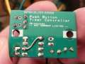
2. What is that black dome in the middle of the board? (Is it doing something to create the lighting effect?)
3. Is there a way to fix this so it's running properly again?
Thanks so much for reading!
Photo #1 shows the internal wiring. From what I've gathered using my multimeter, the lighting (when operating correctly) worked like this: The power comes from three AAA batteries inside a battery holder attached to the PCB. The circuit to the lights is actually complete when the silver button attached to two green wires is NOT pressed. However, if I press & release the button, this interrupts the circuit, which then somehow causes the four Christmas tree lights to power on for 30 seconds. If I were to change the batteries, this would also cause an interruption of the circuit and, likewise, the lights would power on for 30 seconds.
Photo #2 shows the underside of the PCB. There are two transistors and four resistors. Half are used for the positive line to the lights, and the other half for the negative line returning to the battery pack. The negative transistor is marked 58050 D.016 and there are no markings on the positive transistor.
Photo #3 is my best attempt to explain how the electricity flows. (My apologies as I'm not very knowledgeable to draw up a professional-looking schematic.) From what I've discovered, the positive flow (depicted in red) starts off with 4.5v from where the batteries' positive line connects to the PCB and branches off in two paths. Likewise, negative (depicted in black) is returned to the batteries from two separate paths as well. I've noted the voltage in other spots on the PCB as it sometimes changes. Curiously, I measure 0 volts in the bottom right corner. Not sure if this is working as designed, but it remains 0 volts after I press the button now to test. Also worth noting, I drew a green line in the bottom right corner between two solder points. When I physically connect these two with metal, the bulbs light up. (But they only stay on as long as the connection is maintained. There is no "30 second timer" by doing this, and since I'd have to physically press the silver button to break the connection, this method will quickly drain the batteries.)
So due to my limited electronic knowledge I have three questions:
1. How does this board with two transistors and four resistors somehow simulates a 30-second timer to light the bulbs?
2. What is that black dome in the middle of the board? (Is it doing something to create the lighting effect?)
3. Is there a way to fix this so it's running properly again?
Thanks so much for reading!