Need to move a crystal oscillator and overcome extra line capacitance

Thread Starter

Daniel Berwick

Joined Aug 15, 2018
9
Hi everyone,

This is my first post here!

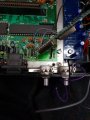
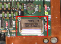
I'm modifying an old console and part of that modification is putting a physical DPDT switch between a 53.2xxxMhz oscillator for PAL and a 53.6xxxMhz one for NTSC. One terminal on the switch physically moves the timing trace from one crystal to the other, and the other terminals send a ground signal to a pin that tells the console it's now running in NTSC mode.

These oscillators, through various multiplications/divisions, control the timing of the entire system. The difference is less than 1% between the two, and the system will run fine in NTSC on the PAL crystal, but the difference in timing causes some on screen artifacts, mostly that jail bars appear on black. These are not ideal so I wanted to allow for a dual oscillator option.

The switch works fine, however in order to use the switch there's extra trace added that's increased line capacitance, about 10CM or so of single cored 22 AWG wire. The problem is, this now causes a rippling effect on screen due to the extra capacitance interfering with the timing signal.

Does anyone have any suggestions for overcoming this issue?

Many thanks,

Dan.
 

MrChips

Joined Oct 2, 2009
30,806
Welcome to AAC!

Don't switch the crystal. Switch the output of the oscillator instead.
In other words, each crystal is wired to its own active oscillator circuit, or use an oscillator module. Select between the two oscillator signals.
 

Thread Starter

Daniel Berwick

Joined Aug 15, 2018
9
Hi MrChips,

Many thanks for your reply. I think I'm basically doing what you suggest (I'll attach the image of the original oscillator here). I'm switching between oscillator signals on 2 oscillator modules with a physical switch.

Basically, I've lifted the existing original module off the board and put it onto a dual board with 2 separate modules. I've run the power and ground traces off the existing mount holes to the correct legs of the oscillators and I'm switching between the output legs to the original output mount hole, so it's directly connected in the same way it would be if it was in its original place. The problem lies (or at least appears to) in the added capacitance in the small amount of wire needed to run to the switch for the output legs.
 

Thread Starter

Daniel Berwick

Joined Aug 15, 2018
9
Quick thought: Do you think a lower gauge cable with a grounded shield for the oscillator output would reduce the capacitance in it enough?

I would assume I can get away with a fairly small wire for this, the load isn't going to high at all.
 
Last edited:

MrChips

Joined Oct 2, 2009
30,806
Two oscillators physically close and at such close operating frequencies may suffer from "pulling", i.e. interference from each other.
Make sure that you have a 100nF ceramic capacitor and a 10μF tantalum electrolytic capacitor across Vcc and GND at both oscillator modules.
Make sure you use heavy wires feeding Vcc and GND pins.
 

Thread Starter

Daniel Berwick

Joined Aug 15, 2018
9
Two oscillators physically close and at such close operating frequencies may suffer from "pulling", i.e. interference from each other.
Make sure that you have a 100nF ceramic capacitor and a 10μF tantalum electrolytic capacitor across Vcc and GND at both oscillator modules.
Make sure you use heavy wires feeding Vcc and GND pins.

Thanks again.

Before I get the iron out and try your suggestion, i had one more idea.

If i have both outputs hard wired, but the Vcc switched between the modules, would that work? It would mean that only one oscillator is active, whilst the other is always dormant. I just wondered if there'd be issues with the return path into the dormant oscillator? And if so, would a diode be too destructive to the output frequency?

Sorry, so many what ifs!

Thank you for the help.
 

MrChips

Joined Oct 2, 2009
30,806
Actually, that sounds like a better idea. You wouldn't know if it would work until you try it.
Instead of two diodes, use two resistors. Try 470Ω resistors for starters.
 

Thread Starter

Daniel Berwick

Joined Aug 15, 2018
9
Boom!

It seems to ground the return path so the 2 resistors are dividing the voltage on the output signal. 470 was too high when dividing, but flawless when only 1 of the 2 was connected.

270 resistor from each output leg directly to the board works a treat though. Problem solved. It's now switchable via Vcc with no significant line interference any more!

Thank you very much for the help
 

MrChips

Joined Oct 2, 2009
30,806
Boom!

It seems to ground the return path so the 2 resistors are dividing the voltage on the output signal. 470 was too high when dividing, but flawless when only 1 of the 2 was connected.

270 resistor from each output leg directly to the board works a treat though. Problem solved. It's now switchable via Vcc with no significant line interference any more!

Thank you very much for the help
Glad to hear it worked for you.
 
Top