 Facebook
 Google
 GitHub
 Linkedin
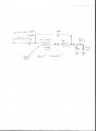
How to use half wave DC 30v pulsing , as already on+ off as "switch", as part of boost converter to be able to get over 100v at 60 cycles on capacitor speed for charging? The inductor is 1.75 millihenry with a diode in front. Current passing through inductor is 6 amps. There is a parallel bypass diode also across the inductor to capacitor. The flyback effect was to go through the bypass diode in reverse to increase volts on the capacitor? 1st diode is the main rectifier, that also blocks the reverse pulse. Is this correct? Power was to go to 5 ohm end load resistor, but at a much lower frequency as 15 cycles switching, at about 100v. I was assuming the cap would charge past 100v during the flyback time of coil as extra pulses, and the 60 cycles frequency, of the power supply shorter time PERIOD . Is this true? In other words, the capacitor is to be charging faster than it is discharging with the electrical load, and accumulating higher voltage.
Attachments
-
 124.3 KB Views: 13
Last edited:


