need help with simple analog to digital interface circuit

Thread Starter

skyline79

Joined Dec 19, 2008
5
Hi, I have a circuit I want to build, I currently Have a working model but would like a suggestion of what you experts (im only a beginner in this field) might think would be the most suitable circuit for the following application……


I have a PNP analogue sensor that gives a 0-10v output.
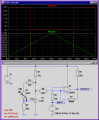
Under test it gave 10.9v out when not sensing, when sensing it droped away towards 0v.
I need to provide a digital signal (0-24 v) when the output from the sensor drops to 10.5 volts.ie: My circuit should output 0v when the anlalog input is 10.9v, and switch to 24v once the analog sensor drops past 10.5v.
The circuit needs to be powered from a 24v supply.

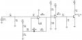
The current circuit I have built is simply a comparator circuit with a voltage reference, using LM358 chip. The output of this circuit (0-24v) then drives a transistor.

I would like it to switch cleanly and quickly if possible.

If you require any other information please ask,
Any ideas would be much appreciated….
Attached is the current circuit I have that works but some values may need adjusting or if someone thinks a complate circuit change is more suitable then please suggest a sdiagram with values for me.... thanks again...

Jason
 

Attachments

beenthere

Joined Apr 20, 2004
15,819
What device will input 24 volts as a logic level? 5 volts is more like it.

You should be able to get a satisfactory result using much lower voltages, plus the use of a voltage comparator for the LM358 should work better.

One more thing - your sensor outputs 0 - 10 volts. Is it a linear output, and why is your output 10.9 volts?
 

SgtWookie

Joined Jul 17, 2007
22,230
You're trying to use an opamp as a voltage comparator. This is a bad idea, and a very common mistake.

Using an opamp as a comparator (open loop) causes the output stage to be in continual saturation; power consumption and resulting heat generation is maximized, leading to a short life. Also, since the opamp is running open loop (no negative feedback) it's bandwidth is severely reduced, leading to slow output transition times.

Look at LM393/LM2903 dual comparators instead. If you don't have that model in your sim, use LM339's. They have open collector outputs, which means that you need to use a pull-up resistor on the output. A good target for the pullup resistor is 3ma to 4ma current. Since you're using a 24v source, a 6k to 8k resistor (inclusive) would provide that range.

[eta]
Did you mean for R1 and R2 to be 1 megohm, or 1 milliohm?
Your simulator will interpret "1M" as 1 milliohm, or 1/1000 of an Ohm. If you meant 1 megohm instead, you must change it to "1MEG"
 

Thread Starter

skyline79

Joined Dec 19, 2008
5
Thanks for your replies,
As you can see I am new to this,

Beenthere...
the sensor is inductive.. Not sure why the output is 10.9 volts when the supply is 24v. The specs are 0-10v.. pnp... on 2 seperate scopes I measured 10.9...

The board that the output of this sensor and circuit is feeding, is a custom board (microprocessor) manufactured for the machine... it basically takes this 0 or 24v input adds time delay and fires some more triacs I think to power up some solenoid valves.

The sensor is not linear.... as the metal approaches the sensor it starts to drop from 10.9 volts, about 5mm closer the voltage is 10.5 volts and thats where I want it to switch. when the metal gets closer the voltage drops away to 0v quite quickly.

SgtWookie,
Thanks also for your reply... I think I may need to do a fair bit more learning and research before I try to jump in...
i did notice heat build up on R5 and changed it to 10k instead of 1k. This circuit will hopefully just plug inline with the sensor and therefore I would like a reliable interface with relativly long lifespan as when installed it is an expensive excersize to access them.
Thanks for the advice on how to display Megohms to.... I did intend it to be Megohms and NOT millohms......


Will take this advice onboard and try again...

Thanks guys,
 

eblc1388

Joined Nov 28, 2008
1,542
My circuit should output 0v when the anlalog input is 10.9v, and switch to 24v once the analog sensor drops past 10.5v.
The circuit needs to be powered from a 24v supply.
I have simulated this circuit and it does what you have wanted. To keep your trip point steady and stable I have chosen to use TL431 to provide the reference voltage of 10.5V. You can adjust this set point accurately via the 2K VR. Right now the circuit will switch at 10.505V and 10.495V so it has a hysteresis of 10mV. If that is not sufficient, you can increase the hysteresis by increasing the R8 470Ω to higher values like 680Ω.


Attachments

Thread Starter

skyline79

Joined Dec 19, 2008
5
Hi,
thanks for your input and circuit eblc1388!! I really appreciate it..
Looks good.... I will patch it together and compare to the results of my first poor attempt when I get a chance!! Im sure it will perform much better!

I have another question you may be able to help me with if you have time. The circuit needs to be able the 0-10v input from a sensor with PNP output and also NPN output (not necassarily the same circuit as there will be one of these per sensor) . The one I explained was PNP output ie: the sensor outputs 10v until it senses metal and then drops away towards 0v.
Hope that makes sense!!!

Regards
 

SgtWookie

Joined Jul 17, 2007
22,230
I have another question you may be able to help me with if you have time. The circuit needs to be able the 0-10v input from a sensor with PNP output and also NPN output (not necassarily the same circuit as there will be one of these per sensor). The one I explained was PNP output ie: the sensor outputs 10v until it senses metal and then drops away towards 0v.
Hope that makes sense!!!
To avoid confusion, you really should start a separate topic for this new question - even though they are closely related. Otherwise, you'll get intermingled responses to your two projects, and you'll have a dickens of a time sorting them out. :confused:

I suggest including a link to this topic, because they are closely related.
 

Thread Starter

skyline79

Joined Dec 19, 2008
5
No problem,
wasn't sure how complicated that question would be and didnt mention that requirement in my initial question....... will see how I go and if im still stuck i'll ask that question in another thread.....
cheers
 

Thread Starter

skyline79

Joined Dec 19, 2008
5
hI GUYS,
i CONNECTED THIS CIRCUIT AS IN THE PICTURE... hOWEVER cAN SOMEONE PLEASE ANSWER ME ON THE FOLLOWING QUESTION.
wHY DOES THIS CIRCUIT NEAR SWITCHOVER GRADUALLY CHANGE. IN THE CIRCUIT DIAGRAM SHOWN IT SWITCHES CLEANLY FROM 0 TO 24V AROUND A SETPOINT OF 10.5V. wHEN i RUN THIS CIRCUIT IN REAL LIFE IT GRADUALLY GOES FROM 0 TO 24V EI: i CN HOLD IT AT 18V OR 15V ETC.... i WOULD LIKE SOMETHING THAT SWITCHES FROM 0 TO 24V BUT NOTHING IN BETWEEN(WELL AS LITTLE AS POSSIBLE ANYWAY)
tHANKS
 

eblc1388

Joined Nov 28, 2008
1,542
How did you test the circuit in real life? What did you use for the input signal?

Try decreasing the 1000K feedback resistor to 330K or 470K for a faster switchover. Decreasing R4 from 12K to 8K2 also helps.

Later I received PM from OP:

PM_Message said:
tHIS IS what I found,
From 10.9v input,183mv output
10.6v> 183mv
10.57v>20.22v output
10.52v>21v
10.5v>23.44v
10.48v>23.44v
10.45v>23.44
NOW GOING BACK THE OTHER WAY(RAMPING THE INPUT BACK UP TOWARDS 10.9V)
10.50V> 20V
10.6V>20V
10.7V>19.2V
10.8V>18.3V
10.9V>17V
10.94V>183mv

As you can see it seems to latch on once it has switched... This test was done with your circuit as is shown in first diagram. the only change was the hysterisis from 1megohm to 220k.
If I used this circuit to drive an optocouple? would this clean up the switch??
I don't quite understand why one would get 17V output at the LM393 output without the LM393 switchover.

There is positive feedback applied at the Non-inv input and the switchover should be instantaneous. :confused:
 
Last edited:
Top