Need help with LM 317 constant current source

Thread Starter

whitehaired novice

Joined Jul 15, 2017
289
I have built a circuit so simple I could not image that anything could go wrong. Ha!

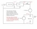
It has a Li-ion cell feeding a boost circuit that raises the voltage to about 28V. This is fed into an LM317 connected as a constant current source with the adjustment resistor variable to make it easy to dial in pretty close to exactly 10 mA. I have not figured out how to move the decimal point on the meter but I have measured the result pretty carefully and it does, indeed, read 100.0X at 10 mA. I was surprised to get four stable digits, expecting to have to put tape over the last two.

The output of the constant current source is connected to one banana jack, the other jack goes to ground which is also the minus terminal of the boost converter.

Across the jacks is a 30 V voltmeter. A shorting switch is across the jacks so it can be closed while I adjust the current to 100.0X.

I had expected the voltmeter to read zero or maybe flutter the fourth digit when the shorting switch is open because there (it seems to me) should be zero current flowing. But actually it is just barely under the voltage at the output of the boost converter; also, the meter reads 000.77 which is .077 mA.

Attached is a copy of the schematic with voltage readings. I have not included in the schematic the power sources which light up the meters but they are completely independent of the circuit.

There is something I don't know or some part of the data sheet I did not read or some other stupid mistake. Help is appreciated.
 

Attachments

panic mode

Joined Oct 10, 2011
2,715
what are the terminals of LM317? how come there a four of them?

if the constant current output is in range 8-12mA, minimum current is 8mA. that is significant leakage current when voltmeter is practically open circuit. this is why without load you see high readings.

why is the amp meter set to 20A when max current is 12mA?

when shorting switch is closed, output voltage as measured by voltmeter must be zero. you are measuring voltage in wrong places (between DC common and Adj terminal which is 1.2V)
 
Last edited:

Thread Starter

whitehaired novice

Joined Jul 15, 2017
289
OOPS. The cap which is drawn as a fourth terminal is mis-drawn--it really goes to the output pin.

The whole intent is to get a 10 mA source. The data sheet seems to indicate this is within spec.

The total range of the meter, as marked, is 19.99 mA. I use it in the 10.00 mA range

The voltage across the jacks is 0 when the switch is closed. The switch was included to make the initial setting of current as precise as possible--and it works; I can get a stable 10.00mA with the fifth digit fluctuating up and down two or three counts. That is a lot better than I had expected.

My problem arises when I put a resistor across the banana jacks (I have, unfortunately, forgotten to say the the circuit is intended as a fairly low range ohmmeter.) I had expected a reading of 1 volt when I put a 100 ohm resistor across the jacks. Not so.
 

AlbertHall

Joined Jun 4, 2014
12,344
It is doing exactly what it should do.
Imagine if, instead of the switch and voltmeter, there was a variable resistor connected to the output.
With this load resistor set to zero there would zero volts across it (I hope that's obvious) and there would be 10mA flowing through it.
Now if the resitance is increased the voltage will begin to rise though the current remains at 10mA.
At 1kΩ for instance the voltage would be 20V as the current is still 10mA. Note that there is now just 8V left across the LM317.
If the resistance is further increased the voltage across the resistor will continue to rise and the voltage across the LM317 will continue to fall. Eventually there will not be enough voltage across the LM317 for it to maintain the 10mA current and the current will now fall as the resistance is increased.

This is the situation with your switch open and the voltmeter connected. The LM317 is doing its best to maintain 10mA but there isn't enough voltage available to drive that current through the voltmeter.

What voltage do you get across a 100Ω resistor?
 

panic mode

Joined Oct 10, 2011
2,715
exactly... also check voltage at A when load is connected or output is shorted. does it stay at 30V? your battery and boost circuit may not be as stable as you expect.
 

Thread Starter

whitehaired novice

Joined Jul 15, 2017
289
I follow your first four lines exactly and that is exactly what is happening and exactly what I planned for.

I am lost on line five: "At 1kΩ for instance the voltage would be 20V as the current is still 10mA" I would expect 1K * 10mA to be 10 volts.

That would leave 18 volts across the LM 317. Further, the resistor controlling the current is adjustable back to the 10 mA.

1 k was about my anticipated upper limit. I actually got reasonably (not satisfactorily) close at 9.663 volts.

A major problem is on lower ohm resistors--the ones this circuit was specifically aimed at--the error is worse.
10 ohms gives me a high reading of 10.39. 2.7 ohms yields higher reading of 0.0304 volts instead of 0.027 and 1 ohm gives 0.0156 volts. Note that this is one of those weird voltmeters which switches range automatically giving greater accuracy below 3 volts than above 3.

Remember, I readjust the meter for 10 ohms for each individual resistor.
 

AlbertHall

Joined Jun 4, 2014
12,344
I am lost on line five: "At 1kΩ for instance the voltage would be 20V as the current is still 10mA" I would expect 1K * 10mA to be 10 volts.
Er... Oops! My excuse is that originally the example was to be 2kΩ.

For the lower value resistors you need to be sure that you aren't including the contact resistance of the resistors. Your readings for the lower values are all high. You need to use the four point measurement system for accuracy. Also what is the accuracy of the resistors?

https://en.wikipedia.org/wiki/Four-terminal_sensing
 

DECELL

Joined Apr 23, 2018
96
So you are adjusting for I=10mA using a zero ohm resistor- the switch.
this is what you would expect:
Image1.png

What input impedance does your 30V voltmeter have? is it shunting away current?
The current sources can oscillate without a cap to ground say 1u- check with a scope
 

Attachments

Thread Starter

whitehaired novice

Joined Jul 15, 2017
289
Well, thanks to those who offered improvements but it is not a better design that I seek but understanding of why the design I have works the way it does. I think I am on a road to understanding it, but my time this morning and maybe this afternoon too is tied up.

So, please make no more replies till I get back-- either with a solution or an explanation of a false trail of thought and a renewed request for help.
 

crutschow

Joined Mar 14, 2008
34,280
I had expected the voltmeter to read zero or maybe flutter the fourth digit when the shorting switch is open because there (it seems to me) should be zero current flowing. But actually it is just barely under the voltage at the output of the boost converter
Of course.
The LM317 is trying it's best to deliver 10mA to the load, so it it applying the maximum voltage it can generate.
 
Top