Facebook
 Google
 GitHub
 Linkedin
Greetings,
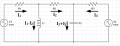
I really need help with some assignments. I am horrible with circuit analysis, so please keep it as simple as possible.
If you have the time, please explain to me, preferably step-by-step how you would solve this using KVL.
We need to find the current running through the equivalent R1+L1 resistor using KVL. Can I apply KVL when there are inductors in the circuit, or do I have to turn them into an equivalent (complex) resistor?

Thank you!
Edit: Deleted 2nd circuit.
I really need help with some assignments. I am horrible with circuit analysis, so please keep it as simple as possible.
If you have the time, please explain to me, preferably step-by-step how you would solve this using KVL.
We need to find the current running through the equivalent R1+L1 resistor using KVL. Can I apply KVL when there are inductors in the circuit, or do I have to turn them into an equivalent (complex) resistor?
Thank you!
Edit: Deleted 2nd circuit.
Last edited: