 Facebook
 Google
 GitHub
 Linkedin
This is my first post but I am desperate for help.
I have a 24VDC Anaheim Stepper circuit that is getting a signal from the relay output of a Mitsubishi PLC. Power is going through a power supply (have already changed this once to eliminate it from the issue) to get me the 24VDC.
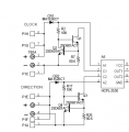
The driver needs a 24VDC signal for direction, but after running for a random amount of time the direction input to the driver fails (two transistors and a Opto-coupler)
Below is the diagnosis from the factory and the driver schematic. I have also attached our wiring diagram.
"It was found that both transistors were shorted and the opto diode was opened. This was mostly caused by an over voltage. I would say the transistors shorted first which then left enough voltage across the diode to open it. I replaced Q3, Q4 ad A5 on both boards. They will finish being tested and then we will burn them again. They will be shipped out tomorrow."
The strangest part is that the clock has not failed.
I have a 24VDC Anaheim Stepper circuit that is getting a signal from the relay output of a Mitsubishi PLC. Power is going through a power supply (have already changed this once to eliminate it from the issue) to get me the 24VDC.
The driver needs a 24VDC signal for direction, but after running for a random amount of time the direction input to the driver fails (two transistors and a Opto-coupler)
Below is the diagnosis from the factory and the driver schematic. I have also attached our wiring diagram.
"It was found that both transistors were shorted and the opto diode was opened. This was mostly caused by an over voltage. I would say the transistors shorted first which then left enough voltage across the diode to open it. I replaced Q3, Q4 ad A5 on both boards. They will finish being tested and then we will burn them again. They will be shipped out tomorrow."
The strangest part is that the clock has not failed.
Attachments
-
 33.4 KB Views: 47
 -
661 KB Views: 21
")


