 Facebook
 Google
 GitHub
 Linkedin
Hi, as the title say it all, I got myself a project that can convert 12V to 24V by simply put the pin in 5v or 0v state.
First of all, I'm using the concept of relay with transistor instead of MOSFET/Power Mosfet to reduce the cost.
Based on my understanding and knowledge;
First of all, I'm using the concept of relay with transistor instead of MOSFET/Power Mosfet to reduce the cost.
Based on my understanding and knowledge;
- We need to put a rated voltage(relay) on the coil pin to magnetised it
- if rated 12V, the coil will magnetised when 12V or more/less 2v+- is supply
- You can see the example on "relay".PNG where the coil will only magnetised when the button is pressed... that is the basic concept
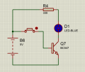
- As for transistor(NPN BC547), to make the current flow from collector(C) to emitter(E) or simply say we need to "ON" the transistor;
- A certain current need to be supply through base(B) in order to "switch it on"
- As for BC547, the output voltage whether on PIC or Arduino is 5v/pin(IO), so it can activate the BC547(even-though it will not fully activate it as the actual Emitter-Base Voltage is 6Vdc
- As you can see on transistor.PNG where no voltage is applied to the base and transistor_On.PNG where there is a voltage on it.
- In order to switch on transistor, the Base(5v) and Emitter(gnd) need to be on the same terminal(battery), we all know that
- What if the Base(5v from MCU) and Emitter(Gnd from the battery) ? it's totally on different terminal to begin with. Does it still work?
- As we need GND for the Current(electron) to flow
- If 12V is supplied, but it connected to GND(MCU), does the electron still flow?
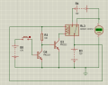
- You can see this problem on transistor_LOGIC.PNG
- Yeah I know the simulation is on PN2222, but since BC547 is the only BJT I got in inventory, so... yeah...
- The coil is not magnetised as it should be if there is no input on the bottom transistor. So, what could be the problem right now as before this designed is fabricated on PCB, I try it on breadboard first and it WORK!
- But when transferred to PCB, its not quite stable as it should be
Attachments
-
 18.2 KB Views: 22
 -
 29 KB Views: 19
 -
 30 KB Views: 20
 -
 33 KB Views: 22
 -
 32.3 KB Views: 23


