I don't see how that could be a factor.
A DC-DC converter can generate noise, but that's totally separate from the diode suppression of the inductive kickback.
I don't see how that could be a factor.
A DC-DC converter can generate noise, but that's totally separate from the diode suppression of the inductive kickback.
I am saying you do not need to connect your scope probe to any part of your circuit. Even if you ground the scope probe to its own ground clip you should be able to pick up transients when your relay switches ON and OFF. What would that tell you about your circuit and EMI?
It will be nice to see your screen shots when you have done this.
Tomorrow I will be able to use the scope and try as you say. Ive been thinking a lot about this, maybe you are right, I just capture EMI produced by the relays and the EMI it is being pickup by the I/O. I am using 100K pulldown resistors so I will decrease the resistors value to 1K and that will help a lot with it. I am not very concerned about power waste as far as this circuit is powered by a big truck batteries
No.
The "ultrafast" is the turn-off recovery time of the diode, which is not of concern in this application.
All diodes turn on rapidly, so an ultrafast or Schottky diode will have little effect on improving the transient suppression.
I agree that the transient you are seeing is likely from the current pulse through your grounds and supply leads when the relay is turned off.
Where did you connect the oscilloscope ground probe?
Try measuring the ground voltage as suggested, and post what you see.
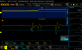
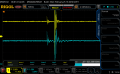
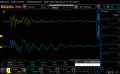
I have been doing some tests to analyze the transients of the relay de-energize as follow:
- Test 1: COM from ULN2003 connected to same rail power of the relays and whole circuit, no external diodes between the relay coil
- Test 2: COM from ULN2003 disconnected (left floating), external diodes (one rectifier 4148 and one zener as posted before)
- Test 3: COM from ULN2003 connected to same rail power of the relays and whole circuit and with external diodes between the relay coil (they should be by-passed more or less by the internal diode of the ULN2003)
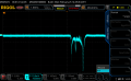
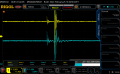
Within the screenshots of the scope you will see one blue channel which is the rail power after DCDC converter (3.3VDC), powering all IC, COM and relay coils; the yellow channel is the main power (12VDC) of the PCB after a common mode noise choke. The activated relay is connected to a load which is a 12VDC a solenoid operated hydraulic valve of a truck (this device is not installed to the truck while the tests, I have with me for testing)
My opinion is that the results are the best when the COM pin of the ULN2003 is left floating and I place external diodes over the relay coils. What do you think?
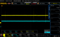
Besides that I attach the measure of the EMI radiated by the relay, to do this I just holded the probe close to the relay. You can see some EMI around and most important the de-energize of the relay
I have been doing some tests to analyze the transients of the relay de-energize as follow:
View attachment 170966 View attachment 170967
- Test 1: COM from ULN2003 connected to same rail power of the relays and whole circuit, no external diodes between the relay coil
View attachment 170965
- Test 3: COM from ULN2003 connected to same rail power of the relays and whole circuit and with external diodes between the relay coil (they should be by-passed more or less by the internal diode of the ULN2003)
Within the screenshots of the scope you will see one blue channel which is the rail power after DCDC converter (3.3VDC), powering all IC, COM and relay coils; the yellow channel is the main power (12VDC) of the PCB after a common mode noise choke. The activated relay is connected to a load which is a 12VDC a solenoid operated hydraulic valve of a truck (this device is not installed to the truck while the tests, I have with me for testing)
My opinion is that the results are the best when the COM pin of the ULN2003 is left floating and I place external diodes over the relay coils. What do you think?
View attachment 170970
Besides that I attach the measure of the EMI radiated by the relay, to do this I just holded the probe close to the relay. You can see some EMI around and most important the de-energize of the relay
I believe what they display is a true representation (zooming into small transients can make them appear important) of the voltage potential between the probe tip and signal ground but for rapidly changing fields like a relay coil that potential (the emf) is not always associated with a circuit current path that is obvious because the measurement instrument probe is a loop into an non-conservative (path dependent) field.
With EMI transients one can never be sure where/how the spikes are getting into the scope.
Is it via the scope probes or the ground and power supply lines?
Often times when my Weller soldering station cycles on/off my scope is triggered and I can see transients on the screen even though the scope probe is not connected to any circuit.

 Facebook
 Google
 GitHub
 Linkedin