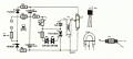
I really have no idea how the circuit should be !
I did my best there, in the woods as I am. Make for me an explicit circuit please. on a piece of paper and take a picture of it.
I can use my variac to slowly and gradually rise up the rectified voltage after a rectifying bridge. Just a thought.
OR
a circuit for a blitz ? I searched myself for one but I didnt get anything useful from google.
Not that way… A variac only works with AC. DC after the rectifier won’t work with a variac. You could put the variac BEFORE the rectifier and filter (you need a hefty capacitor in addition to a bridge rectifier).
q12x said:
I can use my variac to slowly and gradually rise up the rectified voltage after a rectifying bridge. Just a thought.
Not that way… A variac only works with AC. DC after the rectifier won’t work with a variac. You could put the variac BEFORE the rectifier and filter (you need a hefty capacitor in addition to a bridge rectifier).
Those trigger coils are used to get the voltage high enough to flash the lamp. You’re already starting with a high voltage. You also need current and the capacitor supplies that.
Alright ! Thank you for the link page. I believe I can do it.
I just looked into my arsenal and I have Triacs about 20 or so brand new BTA24 600B. And a single scrapped Triac BT137 500.
Also I have 20 or so brand new Diacs DB3.
I do not have those specific components from that diagram. I believe it should work with what I have.
Im putting it here on the table for now.
Also I understood that transformer how to make it as well. I only have to convert SWG into mm for the diameter. That will not be hard. I hope. Hehe.
I just looked into my enameled copper wires (litza in my language)
100 turns 36 SWG = 0.19mm ___ and Ihave: 0.16 OR 0.27
10 turns 22 SWG = 0.70mm ___ and Ihave: 0.87
I think is good enough. with the 0.27 the coil will be more fat but not bringing down the randament of the transformer
with 0.16 the coil will be slimm but im not so sure if it will perform as in the specification page... hmmm?
I guess I'll flip the coin on this.
A Google of "Xenon flash tube circuits" will bring up dozens of examples of flash tube circuits including images of what you have. Next a Google of Xenon flash tube trigger transformers will bring up plenty of 4 to 10 KV trigger transformers. Xenon flash tubes like the one you have typically retail for about $3.50 USD.
A Google of "Xenon flash tube circuits" will bring up dozens of examples of flash tube circuits including images of what you have. Next a Google of Xenon flash tube trigger transformers will bring up plenty of 4 to 10 KV trigger transformers. Xenon flash tubes like the one you have typically retail for about $3.50 USD.
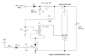
Mister @MaxHeadRoom, I'm building your recommended circuit.
This one extracted from your link page:
- I stay until now; about 2h30m from my last reply and searched for components (choosed and measured). This circuit is a challenge for me. First of all I never ever built such a thing in my life. This is the first time. Its exiting. Very cool. I really hope it will work.
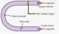
I noticed some special components there. The 10W 470R right in the start of the circuit on the mains line. I had to build one from a couple (3inseries) at 9W and I got very close to 470R but at 9W. I think is good enough. It should be. Also 2 specific electrolytic capacitors at 8uF each. I searched everything I have and I got extremely lucky to find exactly 8uF at 350V for both of them. So this part fit excellent. The 2x12R in line with the diodes, I find 2x10R. I believe they are more like fuses there more than a resistor. I dont think those 12R are critical. Im using the scrapped triac BT137 500. I hope is still good. This part I dont know for sure. Then the 2 diacs are brand new, never used. All I have left to do is to make the transformer now. I find a 0.20mm wire that equivalates the 36 SWG = 0.19mm. So there Im good as well. The 10 turns 22 SWG = 0.70mm ___ and Ihave: 0.87 remains as it is. I noticed the Xenon flash tube has polarity on it's metal band marked. So it is important how to mount it ! Very interesting ! Like a diode or an LED. Also the circuit is telling us it has anode and katode and in the beginning I ignore it to be sincere. But now I know better.
- Uuuh, exciting ! (retorically)It will work ?(retorically) Hehehehe. It better ... haha
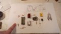
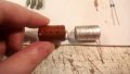
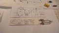
- Ive arranged the components like in the circuit. (except the transformer that I start to make it). I left my finger there in the image intentionally to see exactly the sizes of the resistors. If you see something unfitting, do tell me.
(Zoom into the image for details)
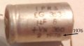
I have a slight problem understanding the polarity of these capacitors.
I believe the aluminium case is the (+). But on the red cap, it actually have (+) and (-) on both sides. That is confusing. They are a tiny bit different in construction. Not the same. Both scrapped as you presumed already.
Ze coil is done ! It looks like a dead bug, haha. I had to add a heat shrink rubber over the first 100turns to keep them in place and not unfold and proper isolate them from this primary coil 10 turns that does not have enamel protection on it at all, thats why I leave a gap between the turns and not squeeze them together. It should work, right? We'll see.
The component layout is done. A lot of work ! And after I make the entire circuit, the lamp is burned !!!!
Because I can not test this lamp otherwise.
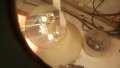
Is this black mark inside the lamp normal? You see on the top leg, inside is a gray spray of metallic paint like. But the bottom leg, inside it, is crystal clean.

 Facebook
 Google
 GitHub
 Linkedin