That's good but may I suggest breadboarding the circuit to see if it's real life performance matches your simulation. I believe there are a couple of circuit elements missing.
I really hate how most of these education-oriented simulators teach bad practices by ignoring real world reality. Particularly since student increasingly get little or no hands on experience building actual circuits.
If anyone there is no any real experiments experience and stable basic theories conception, also he just using the simulators trying to study the EE, I think that situation just like a small house building on the ocean, simulators are the tools, since the simulation tools can not simulate a complete real world, if a EE new learner can't identify the true and fault from the graphics of the results, sometimes it will be as a blind leading another blind.
I heard a situation in some companies, the employees of the simulation departments that they asked the experiments departments to give them some real experiments data, because they need to modified the data for their simulation results.
It's has been happened once before, a user in a forums attached a circuit to asked for help, a helper used the simulation program to simulated the results, he said that the circuit there was no oscillation, but when I did the experiment that it has a slow oscillation, the helper felt very surprised why the circuit could generated oscillation, I thought that he must be trust the simulation software very much, so he can't figure out why and what's going on.
You're missing the point. Have you really learned very much if you are able to make radio buttons that work in a simulator but, because of manifest weaknesses in the simulator, only appear to work within that simulator and will not work if you were to actually build the circuit? What have you accomplished? Unless you are going to spend your career making circuits that will never leave Multisim, you have probably learned more bad things than good. Unfortunately, all too many of the people teaching electronics these days fall into the category of having never built anything except for things that never left a simulator.
I'm saying that, if I were to make this circuit in the real world, I'd probably use physical means (like, literal radio buttons). But this small circuit is just for convenience as means to have only one signal active at a time, I could've used interactive digital constants for all I care.
I'm saying that, if I were to make this circuit in the real world, I'd probably use physical means (like, literal radio buttons). But this small circuit is just for convenience as means to have only one signal active at a time, I could've used interactive digital constants for all I care.
Where would you even find "literal radio buttons" these days? For a one-off project you could probably scrounge something from a decades old piece of equipment. For anything you were to do today you would almost certainly do it digitally. That's what that assignment was supposed to show you how to do. The simulator shows you that it works fine. Then if you (or whoever else) made that circuit they would be coming here wondering why their circuit doesn't work when Multisim "proved" that it was correct. We've seen it time and time again.
This is NOT a rant against you, so please don't take it that way. Though I do notice that you don't seem the least bit curious as to why your circuit won't work in actuality.
Haha actually my assignment is an entirely different thing (a mux/encoder combo for controlling stuff through just 2-3 wires), this is just for convenience, really. And I'd like to know why it wouldn't work in real life, but I don't have any EE equipment at home nor the time to purchase and make anything.
Haha actually my assignment is an entirely different thing (a mux/encoder combo for controlling stuff through just 2-3 wires), this is just for convenience, really. And I'd like to know why it wouldn't work in real life, but I don't have any EE equipment at home nor the time to purchase and make anything.
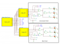
You don't need any EE equipment to figure out the problem. If all of the switches are open, what are the logic levels that are applied to each of the inputs?
No. Open means that no current can flow (the buttons, as shown in your schematic, are open). If the current can flow through the switch then the switch is said to be "closed". Think of a switch that is hinged at one side and looks like a door as seen from above and what it looks like if the door is "open" or "closed". In your schematic, when you close a switch, the right side of the switch is connected to the Vcc line. But what about when the switch is open?
You are making my point beautifully. You are learning to believe that an unconnected logic signal is LO because that is how it is in Multisim. But an unconnected TTL input behaves as though it is HI and an unconnected CMOS input behaves very unpredictably and can even result in damage to the device. But you, and thousands of students like you, are no longer getting the practical, hands-on experience that you need to understand these things and the simulators you are using don't simulate, even to a crude approximation, these very fundamental behaviors of the circuits you are simulating.
To be fair to the simulators, they were never intended to be the only thing that you were exposed to when learning this stuff, thus they were only designed to be faithful to a subset of behaviors. But they are now being used to teach (inadvertently in most cases) things that they were never intended to teach.
I seen college professors who "ignored real world reality" as well in their lab demonstrations. I made a few recommendations to one professor about his teaching style as well as his lab work. He didn't get the point across in the classroom too well and his actions in the lab would have lead students to ignore loading problems that would crop up. Demonstrating requires a "best practices" modus operando. The vast majority of the students had bachelor degrees and the professor was a PHD. In the classroom, I was sitting in the back and a lot of the degreed students turned and looked at me with the deer in the headlamps stare.
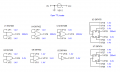
Some simulators will show TTL open inputs high, or more specifically, at the 1.4V described in the Designing with Logic note SDYA009C.pdf from TI or AN363 Designing with TTL from Fairchild.
It's an easy test to see if your simulator allows the open inputs to float.
 Facebook
 Google
 GitHub
 Linkedin