Facebook
 Google
 GitHub
 Linkedin
I had a question to implement this equation through multiplexers,
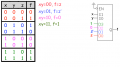
f(x,y,z) = Em (1,2,6,7) but the condition is,
only x and y be the selection line,

see the above picture of my truth table, the 3 data line selector multiplexer is reduced to 2 data lime selector multiplexer , but i am confused how to draw its circuit ? because 'z' is now an input.
how to implement 'z' ??
f(x,y,z) = Em (1,2,6,7) but the condition is,
only x and y be the selection line,
see the above picture of my truth table, the 3 data line selector multiplexer is reduced to 2 data lime selector multiplexer , but i am confused how to draw its circuit ? because 'z' is now an input.
how to implement 'z' ??
Attachments
-
 19.8 KB Views: 335
Last edited: