Facebook
 Google
 GitHub
 Linkedin
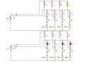
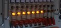
I am looking for advice, corrections, and or suggestions on a project I'm working on. It is basically a fake missile launch control panel (see picture attached). The main idea of the project is that when I turn a three position key switch from off to on #1, power will flow to a set of 4 yellow LED's, each controlled by another toggle switch. So once power is flowing, I can turn the individual LED's on or off, or "enable the missiles" one by one. When I turn the key switch to on #2, I want a second set of LED's (red) to flash to indicate "Launch", and the yellow ones to turn off.
I am very new to this, so I've tried to read and understand what I could about creating the circuit. I also found "Yenka" software to test the circuit and it seems to work (see attached pdf of schematic). Here are my questions:
1. I ran the 4 yellow LED's in parallel, each with its own resistor, since each one is controlled by a switch. Is this correct?
2. Do the 4 red LED's need to be in parallel also (that's how I did it in Yenka), or should I do them in series?
3. I will use a 555 timer chip to control the blinking. Based on trial and error in Yenka I found a combination of resistors and caps to get the pulse I wanted, but how does one figure out in real world what to use. I've seen the formula, but don't understand how to get that in seconds vs. kHz/Hz. Ultimately I'd like to have a three pulse cycle (on-off-on/off-on-off) within about 1 second. What affects it more, the resistors or the cap?
4. Best battery source? I originally thought a 9V battery (space wise good choice), but after reading some it seems like most prefer AA/AAA in series to make 9V. Which is best, since it will only be on short periods at a time.
As far as parts, I think the diagram has values for the resistors and caps; but for LEDs I was looking at 5mm leds, and it seems like both colors are 1.8-2.2 V, and max 20mA. Eventually they will be mounted on a panel, so I'm not sure if I will use surface mount LEDs or basic LEDs with the plastic holders.
Any thoughts, corrections, suggestions are much appreciated. If I left out any info that might be useful, please let me know, although I'm still in the very early stages and may not quite know exactly what I will have to use. Thanks for helping me learn.
Eric
I am very new to this, so I've tried to read and understand what I could about creating the circuit. I also found "Yenka" software to test the circuit and it seems to work (see attached pdf of schematic). Here are my questions:
1. I ran the 4 yellow LED's in parallel, each with its own resistor, since each one is controlled by a switch. Is this correct?
2. Do the 4 red LED's need to be in parallel also (that's how I did it in Yenka), or should I do them in series?
3. I will use a 555 timer chip to control the blinking. Based on trial and error in Yenka I found a combination of resistors and caps to get the pulse I wanted, but how does one figure out in real world what to use. I've seen the formula, but don't understand how to get that in seconds vs. kHz/Hz. Ultimately I'd like to have a three pulse cycle (on-off-on/off-on-off) within about 1 second. What affects it more, the resistors or the cap?
4. Best battery source? I originally thought a 9V battery (space wise good choice), but after reading some it seems like most prefer AA/AAA in series to make 9V. Which is best, since it will only be on short periods at a time.
As far as parts, I think the diagram has values for the resistors and caps; but for LEDs I was looking at 5mm leds, and it seems like both colors are 1.8-2.2 V, and max 20mA. Eventually they will be mounted on a panel, so I'm not sure if I will use surface mount LEDs or basic LEDs with the plastic holders.
Any thoughts, corrections, suggestions are much appreciated. If I left out any info that might be useful, please let me know, although I'm still in the very early stages and may not quite know exactly what I will have to use. Thanks for helping me learn.
Eric
Attachments
-
 60.6 KB Views: 59
 -
41.2 KB Views: 56