MOSFETS heating problem

Thread Starter

syedali

Joined Jun 2, 2014
11
Hi!
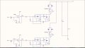
I am designing a shunt regulator which regulates the power from the solar panels. The power that is required by the loads is transferred from the solar panels to the loads and the extra power is dissipated through the shunt regulator unit. The circuit diagram is attached.
The comparator drives the MOSFET IRFZ44N (the datasheet is attached), when the bus voltage exceeds 28 volts the comparator gives high signal and MOSFET gets ON and extra power is shunted through the MOSFET.
Vsupply=12V
My problem is the MOSFETS are getting hot. The comparator having higher Vref (28.1V) gives pwm signal which is given at the gate. The pwm driven MOSFETS are getting hot. The comparator having Vref=28V gives ON signal that is 12V and its MOSFETS are not getting hot. Please help me out in finding the reason why the MOSFETS are getting hot. If anything related to the circuit is not clear please ask. Your help will highly be appreciated.
Thanks.
 

Attachments

bertus

Joined Apr 5, 2008
23,005
Hello,

You can NOT have 28 Volts directly on the input of the opamp, when the powersupply is only 12 Volts.
What is the voltage on the pin Vbus?

Also the gate driving resistors (R4 and R12) are quite large, reduce them to 22 - 100 Ohms.

Bertus
 
Last edited:

pwdixon

Joined Oct 11, 2012
488
Although the spec on the LM358 says it will allow 32V on the input I wouldn't take the input higher than the supply rail for the chip. In fact the spec says keep the input less than 1V below the supply.

Have you checked that the LM358 isn't outputting something higher than 12V as the FETs can only handle 20V on the gate?
 

Thread Starter

syedali

Joined Jun 2, 2014
11
I have scaled down my voltage levels within the supply limits by using VDR (voltage divider). The scaling factor is 8.333333 so for getting 28V, I have used Voltage divider resistor values to get 28/8.333333 = 3.36V. Vbus is also applied after scaling down. I didn't show it there so that my schematic would not look complex.
---
Also the gate driving resistors (R4 and R12) are quite large, reduce them to 22 - 100 Ohms
Ok, i'll check after replacing the resistors.
---
Have you checked that the LM358 isn't outputting something higher than 12V as the FETs can only handle 20V on the gate?
The lm358 is outputting high level of 11.8V
 

BobTPH

Joined Jun 5, 2013
11,643
If you are shunting power directly to ground through a MOSFET, of course it is going to get hot, where else would the power be going?

Bob
 

Thread Starter

syedali

Joined Jun 2, 2014
11
The mosfets are damaged after getting too much hot. Also if the single mosfet is used to dump the extra power, it is not getting hot But if two parallel mosfets are used then the mosfets are getting too much hot. Why is it so? Is there any alternate method to dump the extra power of the solar panels?
 

pwdixon

Joined Oct 11, 2012
488
Something doesn't sound right here.

How much current are you expecting the fets to pass?

As the fets are spec'd for 0.017 Ohms RdsON for these devices to get worryingly hot you probably would need to have say 0.5W dissipated, that's 5 amps.

There are other fets out there that have lower RdsON figures or alternatively you could add a heatsink.
 

BobTPH

Joined Jun 5, 2013
11,643
There is something I am not understanding here.

If you are shorting a 28V rail to ground and 2.5A is following, that is 70W. Where is that power going?

Bob
 

Thread Starter

syedali

Joined Jun 2, 2014
11
There is something I am not understanding here.

If you are shorting a 28V rail to ground and 2.5A is following, that is 70W. Where is that power going?

Bob
The whole solar panels' power is not shunted, the power is first transferred to the loads and then the extra power is shunted through the mosfets.

Thanks all for your help. I have tried the gate driver circuit by using 7406 schimmit inverter (given in some book), now the MOSFETS are not getting hot.

The next step is to design DC bus capacitor bank which I have shown in the schematic as C3. The purpose of this capacitor bank is to remove the ripples and provide constant 28V at the bus. I have got this formula to calculate the capacitance value;the peak to peak ripple output voltage is given as,
Vpp= Isc*Rc + (D(1-D)*Isc)/(C*fs)
if D=0.5,
Vpp= Isc*Rc + (0.25*Isc)/(C*fs)
so, the capacitance is calculated as,
Cmin ≥ (0.25*Isc)/((Vpp-Isc*Rc)*fs)
where,
C= capacitor bank value
fs= PWM switching frequency
Vpp= maximum ripples at the output before the capacitor
Rc= ESR (Equivalent series resistance) of the capacitor
Isc= short circuit current of the solar panels or the current that is shunting
Here, Isc and Vpp are known but I am confused about the values of fs and Rc as the switching frequency (fs) of the PWM is changing as the load changes. Please tell me any method to determine the value of capacitor bank.
Thanks.
 
Top