MOSFET heating up too much ????

Thread Starter

dlpweb3

Joined Jan 5, 2012
16
To: AudioG

I guess you have put your finger on where I am off base. My boss asked me to put together a switch for the blinking light, but his box actually has THREE lights and they share a common ground. So, I have no idea how to isolate the ground (and switch it on the low side) just for my one bulb. I thought of using a pnp mosfet, but it seems there are few/none that will handle much in the way of current. That's why I've been trying to figure out how to use an npn device to essentially do high side switching.

Should I be thinking instead of an igbt?


at this point i'm pretty stumpted.
 

Thread Starter

dlpweb3

Joined Jan 5, 2012
16
There are three lights I ultimately will need to switch - each 50w.

One shines down the left hallway; another down the right hallway. These are discrete and I can get to the ground of these. So, I suppose i can use the MOSFET for these.

But the other light shines straight forward and has 2 filaments - one on normally and the other flashing (when the alarm has been triggered). This is a 'sealed beam' thing that shares a common ground, and i have no idea how to do low side switching on this one w/o screwing up the main filament's light. The left and right bulbs are only on when the alarm has been triggered and have only the single filament).

Maybe I have to use both npn and pnp fets ... but i was thinking there MUST be a more 'professional' solution than that.
 

praondevou

Joined Jul 9, 2011
2,942
You can use a High-side switch, a p-channel MOSFET. High lamp inrush current should be less of a problem because the MOSFET is being rapidly turned on.


Attachments

thatoneguy

Joined Feb 19, 2009
6,359
If you are inside the unit, can't you isolate the ground lead leading to each bulb and insert the MOSFET in the cut wire leading to that particular lamp?

It would simplify things greatly. I'm guilty of not looking at your schematic close enough, and Audioguru found the issue.
 

Thread Starter

dlpweb3

Joined Jan 5, 2012
16
On 2 of the 3 lamps - yes, I can get to the ground wires and use a low side switch. On the main lamp I can't - which is what has caused this problem all along.

So - one last time before giving up - is there a way to do high side switching w/o all the pnp drawbacks?

Praon - this looks like (maybe) it might allow use of an npn on the high side (like the driver you suggested w/ charge pump but for high side apps):

http://www.micrel.com/_PDF/mic5014.pdf

is that correct?
 

Thread Starter

dlpweb3

Joined Jan 5, 2012
16
sorry about the 'giving up' thing. it's just the level of knowledge and understanding you and others here have is so far beyond mine it's embarrassing to ask.

when you said, "prob not needed" --- do you mean a driver would not be needed at all for this application ---- just wire up the mosfet on the high side? But, I thought that is what I was doing 9and did not work because of turn on/off problems)?
 

thatoneguy

Joined Feb 19, 2009
6,359
Before we go further, I'd like to ask one question:

Are these the primary safety/fire lights that illuminate exits in an emergency? If so, you shouldn't tamper with them at all, because if your mods cause one to fail, people could die, and that's a bad thing.
 

praondevou

Joined Jul 9, 2011
2,942
when you said, "prob not needed" --- do you mean a driver would not be needed at all for this application ---- just wire up the mosfet on the high side? But, I thought that is what I was doing 9and did not work because of turn on/off problems)?

Ok. There are many different types of transistors. The two main types you have to distinguish here are n-channel MOSFETs and p-channel MOSFETs.

To both you need to provide a voltage Vgs, from gate to source, for NMOS it's a positive voltage to turn it on, for a PMOS it's a negative voltage.

In AG's schematic the NMOS' source is connected to Gnd, in my last schematic the PMOS' source is connected to +12V.

Apart from the fact that in your very first schematic the gate resistors were quite high, the load was also between source and Gnd which, as AG pointed out, is incorrect.
In other words you didn't provide the correct voltage from Gate to Source of the NMOS.

Now the PMOS is switched with a signal from gate to source too, only that the source is more positive than the gate because the source pin is connected to +12V, right?

The PMOS will turn on when its' gate is pulled to Gnd via the npn- transistor and off when it's gate is discharged through the 4k7 resistor.

It's like the NMOS but the other way around.

-----------------------------------------------------

You can also use a NMOS as a high-side switch, but you need to make sure to provide the correct voltage from gate to source,i.e. at least 10V to 15V.

As for the turn-on/turn-off times: For switching applications in general it is desirable to switch fast from on state to the other.
The main losses in the MOSFET are due to switching losses and its' On-resistance.

The switching losses should be really low since your frequency is low AND with the PMOS the gate is turn on fast. I actually would add a small gate resistor for that, I forgot to draw it.

And, last but not least, the light bulb does indeed have a lower resistance when cold.
 

Thread Starter

dlpweb3

Joined Jan 5, 2012
16
Thanks, Praon.

I guess the easiest solution would be to use a PNP mosfet, but (as i understand it) the RDSon is worse than with NPN and also (as far as I saw on DigiKey) there really are not comparable high current PNPs (oh - and they seem a lot more expensive).

To use an NPN on the high side i would HAVE to have the kind of driver you suggested - right? (except one for a high side application). If that is the best path, I'll put together a stab at a circuit so this is on more concrete terms. Is that best?

for ThatOne: No, not for exit lighting. They asked me to do this for an alert light that is triggered by a security alarm. And I really would like to be able because it's really hard finding a job right now, and without a job i can't pay tuition and get back in school. So ... I'm trying as best as i can ...
 

PaulEE

Joined Dec 23, 2011
474
Take a look at this...

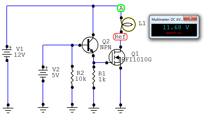
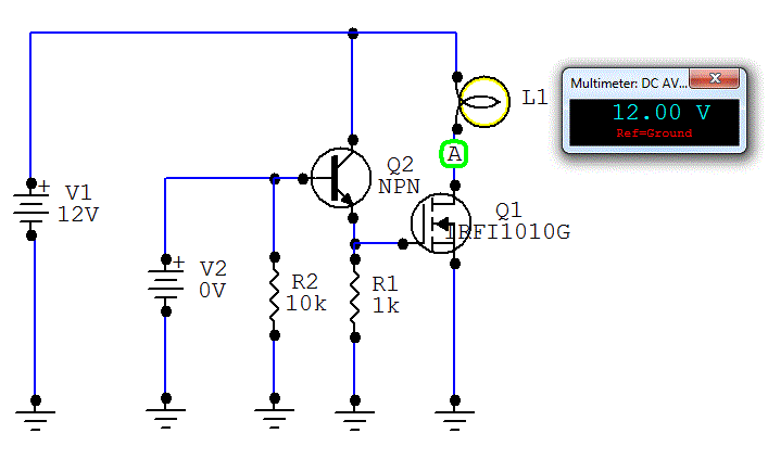
Circuit is either on (+5v logic signal on base of NPN) or off (0v logic signal on base of NPN). Note the voltage drops on the bulb and mosfet in each case. Note that power dissipation is maximum in bulb, minimum in mosfet, and non-existent in the off condition.

On:


Off:


Note that you can build THE SAME CIRCUIT AS MANY TIMES AS YOU WANT and, as long as your +12v source can supply the current, you can switch on and off as many light bulbs as you want independently. You just need one circuit per bulb and a corresponding on/off signal.

Get it?
 

Thread Starter

dlpweb3

Joined Jan 5, 2012
16
Hi PaulEE

Thanks so much for the suggestion.

My problem is that I can't get access to the ground wire and have to have a high side switch.

Do you know of a way to do this w/o using a PNP mosfet?
 

praondevou

Joined Jul 9, 2011
2,942
Hi PaulEE

Thanks so much for the suggestion.

My problem is that I can't get access to the ground wire and have to have a high side switch.

Do you know of a way to do this w/o using a PNP mosfet?
The term "PNP" is used for bipolar transistors. It's "p-channel" MOSFET.

To use a n-channel MOSFET as the one you have the gate voltage needs to be higher than the supply voltage, therefore you need a charge pump (high side driver).

12V over the load connected to the source, means you need another 12V to drive the gate, the gate will then be 24V over gnd and 12V over the source voltage level.

There are suitable PMOSFET available on digikey.
 

Thread Starter

dlpweb3

Joined Jan 5, 2012
16
Thanks again, Praon. I've thanked you before, but hope you realize just how much I appreciate your help and knowledge.

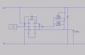
Think I'll try a high side driver (thinking of an IR2117) since the p-channel mosfets seem to have both an inherent RDSon disadvantage (heating, I presume) and lower current capability .... while costing more. The cost is probably not a factor since the addition of a driver to be able to use an n-channel mosfet wipes out the cost advantage.

Won't have the parts for a day or two to see how it works, but in the meantime:

this look OK for my breadboard circuit (still need to figure out the R & C values)?:
 

Attachments

praondevou

Joined Jul 9, 2011
2,942
Thanks again, Praon. I've thanked you before, but hope you realize just how much I appreciate your help and knowledge.

Think I'll try a high side driver (thinking of an IR2117) since the p-channel mosfets seem to have both an inherent RDSon disadvantage (heating, I presume) and lower current capability .... while costing more. The cost is probably not a factor since the addition of a driver to be able to use an n-channel mosfet wipes out the cost advantage.

Won't have the parts for a day or two to see how it works, but in the meantime:

this look OK for my breadboard circuit (still need to figure out the R & C values)?:
Yes the IR2117 circuit looks ok. Note that the capacitor C4 is being charged through the load when the MOSFET is OFF. There will be a self discharge of this capacitor and also through the driver I guess. I have no idea how long the voltage at the power MOSFETs' gate will be at the necessary level (maybe someone else has). You will need to try it out.

Mount C1 near the MOSFET/LAMP. Keep the path from driver to gate and back short.
 

Thread Starter

dlpweb3

Joined Jan 5, 2012
16
Thanks!

I contacted customer tech support @ IR, and they sent a design datasheet but it was about using a high side driver with an IGBT, and I have no idea how applicable it is (or if i should be thinking of an IGBT instead of a mosfet). Asked for something for use with a mosfet; hopefully they will have one (and I can understand it at least in part).

Looking forward to breadboarding. Nice being able to learn!
 

praondevou

Joined Jul 9, 2011
2,942
Thanks!

I contacted customer tech support @ IR, and they sent a design datasheet but it was about using a high side driver with an IGBT, and I have no idea how applicable it is (or if i should be thinking of an IGBT instead of a mosfet). Asked for something for use with a mosfet; hopefully they will have one (and I can understand it at least in part).

Looking forward to breadboarding. Nice being able to learn!
You really should be good to go with the MOSFETs you have, they are more than capable to drive a lamp like this.
It's just important to drive them properly. (and to use an appropriate heatsink if necessary)
 
Top