Mosfet H-Bridge: Hot P-Channel FETS

Thread Starter

Brotherspoon

Joined Jan 13, 2018
11
Hello AAC folks,
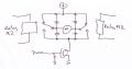
I've designed this h-bridge circuit to run a 60v brushed shunt motor that is controlled by 12v stop-start circuitry, the relay logic prevents catastrophic shoot through (forward and reverse conditions simultaneously)

The tl494 is driving the two n-fets with a 10KHz pwm square wave.
The tip31c's pull down on their collector dividers to apply approximately 10v to the p-fet gates with respect to the source (60v).
The bd136's drive the gate of their respective n-fet, when on, the n-fet gates sit at 0.6v

When running "forwards" (push button FS "forward start" is pressed) , FI2 NO closes turning on the upper tip31c and brings fet F1 Vgs to 10v, turning it on fully.
The lower bd136's gate is brought up to 12v, the transistor turns off and brings fet F2 Vgs to somewhere between 1-10v (depending on the pwm duty cycle), this is all good, the motor runs with adjustable speed. The problem is that the other p-fet R1 gets instantly hot even though its gate stays at 60v (Vgs = 0) in this condition, when inadequately heat-sinked , the fet burns up and shorts out after 5-8 seconds. (F1 and F2 do not get hot)

The same condition happens when going in reverse, this time p-fet F1 burns up

Does anyone know what is happening here?
Thanks!

(PR-1 and 2 NO contacts are a power relay that is energized in both direction conditions, consider it always closed or not there for this)
 

Attachments

dendad

Joined Feb 20, 2016
4,634
For a start, add 10K resistors between the base and emitters of the driving transistors. It is good practice to not leave base connections open.

But if you are using relays, why not have then do the H bridge and just have a single FET for the PWM?
Using relays defeats the whole point of a FET H bridge.


RelayH-Bridge-PWM.jpg
 

Attachments

Last edited:

Thread Starter

Brotherspoon

Joined Jan 13, 2018
11
I can certainly appreciate the suggestion, its a valid point, but the amount of relays to make a direction bridge would be more than i have now, though it could be streamlined down to something nifty and efficient i suppose.

Are you talking about both the npn and pnp pairs?
Thanks
 

dendad

Joined Feb 20, 2016
4,634
I can certainly appreciate the suggestion, its a valid point, but the amount of relays to make a direction bridge would be more than i have now, though it could be streamlined down to something nifty and efficient i suppose.

Are you talking about both the npn and pnp pairs?
Thanks
Anytime you have a transistor or FET, it is a good idea to have a termination resistor, for want of a better name, on the input so it is always at a defined level. Floating inputs can give some very odd behaviors.

You only need 2 relays for the bridge itself. Turn one on for forward, the other for reverse. Both on or both off will cause no problems, just short the motor so it has braking.
That does not count what your control system is.
 

dendad

Joined Feb 20, 2016
4,634
Like this?
RelayH-Bridge-PWM-2.jpg
(Please forgive my sloppy hurried circuit )
When you push a button, a relay is operated and power is fed to the PWM generator. Letting the button go and it will stop.
 

dendad

Joined Feb 20, 2016
4,634
Oh, put a NC switch in line with each push button that operates at the limits of the travel to automatically stop the motor if that is applicable.
 

Thread Starter

Brotherspoon

Joined Jan 13, 2018
11
I know it will work! It's pretty much fool proof that way, however i was wondering about the heat in the p-fet, i know that a dedicated bridge driver ic would mitigate this issue, but what is causing it?, is it due to the non-terminated base of the driver transistor associated with the other p-fet? I am really curious about it, and it begs the appropriate question... y tho :)
 

ebp

Joined Feb 8, 2018
2,332
Judging by the way you report the gate voltage of the PWM'd FET, I take it you are measuring the voltage with a meter. This really isn't very instructive. I suspect the P-channel device that should be off is being partially enhanced by the chopped voltage on the drain capacitively coupled to the gate.

4.7k gate to source is possibly too high to assure the gate doesn't get pulled past the threshold voltage. In any case, circuits like this are layout sensitive and the gate-source resistors must be right at the gates, not at a distance via an inductive path.

As long as you aren't switching the P devices when they are carrying current, you could try adding significant (e.g. 50 nF or more) capacitance between the gate and source of each, again, right at the FET. This will make switching slower (presumably not important) but could provide a clue about what is going on. If it reduces heating in the FET that should be off, it suggests more strongly that the gate is getting pulled down via gate-drain capacitance (the added capacitor lowers the gate-source impedance at high frequency without requiring reduction in the gate-source resistance - it "eats" some of the spike energy then allows the resistor to dissipate that energy over the rest of the cycle). Even if the capacitance wouldn't be acceptable in normal operation, adding it is an experiment that may yield a clue.

Another option is to simply reduce the gate to source resistor on the FET that should be staying off - again, just as an experiment.

Unfortunately, circuits like this are difficult to assess without an oscilloscope with good bandwidth, and even then are difficult because you need to look at signals relative to points that aren't "ground" (e.g. the P gates relative to their sources). A current probe is a very useful thing, but they cost a lot more than a pretty decent digital oscilloscope.
 

Thread Starter

Brotherspoon

Joined Jan 13, 2018
11
I believe your initial suspicion to be correct because when the pwm duty cycle is at 100%, the heating effect in the p-fet is almost entirely diminished
Your response is great, thank you. I will experiment with the resistance values and some decoupling capacitors
 

Sensacell

Joined Jun 19, 2012
3,768
The RC time constant of the 22 K ohm resistor and the gate capacitance is causing the the gate voltage to transition too slowly from high to low.
The PFET spends a large portion of each cycle dissipating power because it's neither 100% on or off.

You need to reduce the gate resistor values substantially, or use a gate driver IC to speed up the transition.

That's why the idea if using a single NFET with relays to reverse direction is not a bad one, it's easier to drive the gate of an NFET with the source grounded hard and fast.
 

dendad

Joined Feb 20, 2016
4,634
If you want to use your circuit, just switch the PFET you need on and PWM only the NFET.
You do not need to PWM both.
 

Thread Starter

Brotherspoon

Joined Jan 13, 2018
11
I am switching one p-fet completely on and pwm-ing the corresponding diagonal n-fet only.
The p-fet driver transistors are driven by 12v from the 317. So the p-fets are either fully on or fully off.
The n-fet driver transistors are driven by 12v also, but the emitters get pulled high when switched off and pwm the gate of the associated n-fet
 

Thread Starter

Brotherspoon

Joined Jan 13, 2018
11
I reduced the ratio of the p-fet gate resistors to 1k and 4.7k to get the same Vgs, the heat in the p-fet has been reduced significantly, it no longer burns up, even at very low duty cycles (where it would normally get destroyed in seconds)

The issue now is balancing the power dissipation of the divider strings and the p-fet temperature rise.

I will experiment with capacitors around the p-fets
 
Top