Mosfet circuit question

Thread Starter

brianium

Joined Aug 26, 2020
13
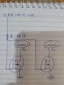
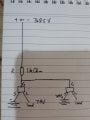
Hi. I would like some advice on setting up a circuit to turn two cameras on one at a time depending on whether the signal voltage is negative or positive. I have attached the circuit diagram. The mosfets that were the closest to the voltage I am working at are A7SHB p-channel an A4SHB n-channel both rated at 30V. The voltage source of signal and source is between 6.5 and 8.5 V (2cell lipo) and current less than 1 amp. I have not been able to get this to work. Can someone please give me some advice on the suitability of these mosfets and alternatives that may be more suitable. Also does the circuit need any alteration to work properly. Thanks in advance, Brian.
 

Attachments

jpanhalt

Joined Jan 18, 2008
11,087
I cannot tell what you are trying to show. Please post a schematic using accepted symbols for devices, common grounds, etc.

From what you show, it will not work. Mosfets are controlled by the potential difference between the source pin and gate pin.
 

KeithWalker

Joined Jul 10, 2017
3,063
How is the input signal reference connected to the FETs? we only have a small part of the picture so I can not offer any suggestions.
Keith
 

Thread Starter

brianium

Joined Aug 26, 2020
13
I cannot tell what you are trying to show. Please post a schematic using accepted symbols for devices, common grounds, etc.

From what you show, it will not work. Mosfets are controlled by the potential difference between the source pin and gate pin.
This is the best I can do. I am only new to circuitry.
 

Attachments

Thread Starter

brianium

Joined Aug 26, 2020
13
How is the input signal reference connected to the FETs? we only have a small part of the picture so I can not offer any suggestions.
Keith
The signal reference is connected by solder joints to the resistor and FET. It is a straight dc voltage between 6.5 and 8.5V.

Are all the voltages coming from the same battery?
Can the signal directly power the cameras?
There is only 1 battery in the system which powers the the signal and the cameras, switched by the FETs. The source terminals are powered directly by the battery.
I was thinking I might need to place resistors between gate and source to remove stored power and allow the FETs to switch off?? It seems the FETs aren't switching off with the above circuit.
 

Alec_t

Joined Sep 17, 2013
14,280
..... or you could use just a pair of diodes (e.g.Schottky type) instead of the FETs in the post #8 circuit.

Edit: I don't think the FETs in the post #8 circuit ever switch on. It's the FET body diode currents which power the cameras.
 
Last edited:

crutschow

Joined Mar 14, 2008
34,280
I don't think the FETs in the post #8 circuit ever switch on. It's the FET body diode currents which power the cameras.
But they do turn on.
Look at the Vgs voltages of the MOSFETs.
At start-up the body diode does initially carry the current but when the MOSFETs' Vgs exceed their threshold value the MOSFETs turn on.
MOSFETs conduct equally well in the forward and reverse direction when on.

In the simulation below, the ON voltage drop for M2 is <29mV, so obviously the MOSFET is conducting.

1598542581068.png
 
Last edited:

Thread Starter

brianium

Joined Aug 26, 2020
13
But they do turn on.
Look at the Vgs voltages of the MOSFETs.
At start-up the body diode does initially carry the current but when the MOSFETs' Vgs exceed their threshold value the MOSFETs turn on.
MOSFETs conduct equally well in the forward and reverse direction when on.

In the simulation below, the ON voltage drop for M2 is <29mV, so obviously the MOSFET is conducting.

View attachment 215757
Crutschow, what simulator program do you use?
 
Top