Mosfet as Reverse Polarity Protection

Thread Starter

Dmm

Joined Apr 13, 2015
70
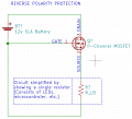
I'm making a circuit which includes a mosfet to protect against reverse polarity. Just need help confirming I'm understanding what I need to know. I'm looking at using the FDC610PZ.

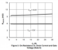
My circuit will require around 4 A to 5 A total (I can adjust this if needed) so I need to look at ID (Drain Current) and make sure the value in the datasheet is higher than what my circuit requires? The FDC610PZ lists -4.9 A drain current, so I think I should stay to the 4A max draw on my circuit. Is this correct?

Next question: By the drain current value, the datasheet has "note 1a" noted. This talks about mounting the device on 1 square inch copper pad, and note 1a and 1b have a diagram. I'm not 100% sure what I'm looking at, but does this mean to run that high amps (4.9A) it needs to be soldered to this 1 sq.in. copper pad for thermal dissipation? What is the 1b note showing? Would I be better off using a TO-220 mosfet to avoid needing the 1 sq.in. copper pad? Any recommendations?

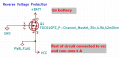
Shown in the attachment is my setup:
Drain = +12v battery
Gate = Ground
Source = voltage out to my circuit

PS I've read about using a resistor and Zener diode between gate and source, but I'm leaving it off for simplicity and assuming the user (me!) will only use 12v battery.
 

Attachments

MrSalts

Joined Apr 2, 2020
2,767
A single Mosfet is not a good solution for reverse polarity protection. The so-called "body diode" is an inherent feature/incombersnce of mosfets. If reversed biased, current will flow through that diode. See your image for reference of the body diode you posted.
to protect from reverse biase, you'll need two mosfets in series (tail-to-tail) and then control the gate of the Mosfet that has reverse biased body diode. Let current flow through the body diode of the second Mosfet.
This two-Mosfet strategy lets you charge and discharge your battery as well.
 

Thread Starter

Dmm

Joined Apr 13, 2015
70
From my understanding, if my example is connected in reverse (+12v on gate, ground on drain) that “turns off” the mosfet. And when connected properly with +12v on drain and ground on gate, it turns on the mosfet and you get voltage at the source. This is following an example on TI website, various YouTube videos, and other websites.
 

MrSalts

Joined Apr 2, 2020
2,767
From my understanding, if my example is connected in reverse (+12v on gate, ground on drain) that “turns off” the mosfet. And when connected properly with +12v on drain and ground on gate, it turns on the mosfet and you get voltage at the source. This is following an example on TI website, various YouTube videos, and other websites.
Yes, that is how a Mosfet works in normal bias but your question asked about reverse bias (reverse polarity protection).
 

Thread Starter

Dmm

Joined Apr 13, 2015
70
Yes, that is how a Mosfet works in normal bias but your question asked about reverse bias (reverse polarity protection).
I think this part is confusing me: “If reversed biased, current will flow through that diode.” I read that and think you meant my circuit would turn on (voltage at my Vcc point.) Also, I may be using the term Vcc in my example incorrectly? I’m not applying a voltage at where I have Vcc noted, it’s just a name I used to indicate where the rest of my circuit will go in the schematic. The only place voltage will be applied is at the gate (incorrectly connected) or the drain (correctly connected.)
 

crutschow

Joined Mar 14, 2008
34,464
Yes, one P-MOSFET will work for reverse polarity protection, you don't need two.
It conducts the supply current normally in the reverse direction (substrate diode forward biased) since MOSFETs conduct equally well in either direction when biased ON.
If the supply is reversed (P-MOSFET normal direction) then the MOSFET is biased off and does not conduct.

You should pick a MOSFET with an on-resistance such that it will dissipate no more than about 1/2W to avoid needing a heat sink.
For 5A that would be an on-resistance of no more than 20mΩ.
 

Thread Starter

Dmm

Joined Apr 13, 2015
70
I attached a new schematic that shows the circuit better. I am powering the entire circuit with a 12v battery, then using the MOSFET for reverse polarity protection. The resistor shown in the attachment just illustrates where my main circuit/parts will be in relation to the battery and MOSFET. My circuit will have a microcontroller, LEDs, buttons, etc. so the resistor shown is just to simplify it for discussion.

@crutschow thanks for the advise on the 1/2 W and RDS(on) suggestions.

One of the videos I saw on this type of circuit used the IRF5305 and it is available at some online parts stores. This has RDS(on) of 60 mΩ so if I limit my current to 4A, P=4A x 4A x 0.06 Ω = 0.96 W or limit to 3A would be 0.54 W.

How do I look at the datasheet to see if I need a heat sink? I know the easy answer is just pick one with RDS(on) with what you suggested. And I'll dig around the sites to see what other part numbers might have something lower if I want the higher 4A in my circuit. Just trying to understand it better.
 

Attachments

Thread Starter

Dmm

Joined Apr 13, 2015
70
I found a couple pages that talk about the thermal parameters, and I think I have a better understanding to answer my question about if a heat sink is needed.

Using the IFR5305 for an example, the datasheet shows Junction-to-ambient of 62 C/W, and RDS(on) of 0.06 ohm. So, if I run it at 4A, then P = 4x4x0.060 = 0.96W. I then multiply that by the junc-to-amb value 62 C/W and that gives me 0.96 W x 62 C/W = 59.5 C. So if ambient temp is 30 C, the junction temp will then be 30 + 59.5 = 89.5 C.

The datasheet has "Operating junction temp" shown as -55 to 175 C. So I should be fine without a heat sink as long as that calculation stays below 175 C. Correct?
 

crutschow

Joined Mar 14, 2008
34,464
The datasheet has "Operating junction temp" shown as -55 to 175 C. So I should be fine without a heat sink as long as that calculation stays below 175 C. Correct?
Not quite.
Look at Figure 4 in the data sheet.
The ON resistance goes up with temperature, so the actual temperature may be significantly higher.
For example the Rds(on) is about 1.5 times the 25°C at 115°C, which now gives a power dissipation of 1.44W at 4A, and a rise above ambient of 89°C, worst-case.
That's getting pretty toasty. :eek:
For good reliability, I would not run the transistor that hot.
 

Thread Starter

Dmm

Joined Apr 13, 2015
70
Not quite.
Look at Figure 4 in the data sheet.
The ON resistance goes up with temperature, so the actual temperature may be significantly higher.
For example the Rds(on) is about 1.5 times the 25°C at 115°C, which now gives a power dissipation of 1.44W at 4A, and a rise above ambient of 89°C, worst-case.
That's getting pretty toasty. :eek:
For good reliability, I would not run the transistor that hot.
Thanks for that tip, that makes sense. So you then have to iterate a few times to see where the temp stabilizes? Looks like for my example it's around 122 C. Under the max in the datasheet, but really hot.
 

Attachments

Thread Starter

Dmm

Joined Apr 13, 2015
70
I'm back looking at what parts may work for me, I found this one, AOI21357 (datasheet link, Digikey link), should do the trick, maybe? It has very low RDS(on) of 8 mOhm, and at less than a $1 per unit. Is there anything I am missing, or that I don't know about MOSFETs for this use, why I shouldn't use this part?

The only thing I'm seeing that I might not understand is the RDS(on) in the datasheet is listed at conditions "VGS=-10v, ID=-20A". I should be around 12v and somewhere between 3A to 5A. I first saw the chart (attached) for RDS(on) vs ID and this shows a flat value for RDS(on) across the entire chart. But Note E states: "The static characteristics in Figures 1 to 6 are obtained using <300 ms pulses, duty cycle 0.5% max"

With the low RDS(on) of 8 mOhm, or even up to 13 mOhm, and a max of 5A circuit, the power would be 5x5x.013 = 0.33 Watt. Do I just take @crutschow general advice stay under 1/2 W and move on and call it a day? I'd like to know more about that "conditions" the datasheet shows I mentioned above. I just wish there was a chart that didn't have pulse values for RDS(on) vs ID. Or is there something else I should be looking at?
 

Attachments

crutschow

Joined Mar 14, 2008
34,464
stay under 1/2 W and move on and call it a day?
That should be fine.
At 12V your maximum on-resistance will be 8mΩ with a 5A power dissipation of 200mW.
The steady-state thermal resistance of the MOSFET to air is 50°C/W max, giving a temperature rise of 10"C, so just warm at room temperature.
I'd like to know more about that "conditions" the datasheet shows I mentioned above. I just wish there was a chart that didn't have pulse values for RDS(on) vs ID
Not a significant factor.
They test under short pulse conditions so the transistor doesn't have time to warm up from the dissipation and affect the measurement values (for example, Rds(on) increases some with temperature, going to 11.5mΩ max at 125°C).
 
Top