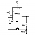
Momentary switch to power ON a circuit

Thread Starter

Forcerouge

Joined Jun 29, 2024
14
Hello Everyone,

I'm a noob trying to learn electronics
I'd like to make something extremely basic: a simple momentary switch in order to switch ON and OFF a small fan and a status LED.
The thing needs to be powered by a lithium battery, so with voltages ranging from 4.2V to 3V or so.

I have a small charging system (TP4056) and a small BMS system (DW01A with a 8205A dual mosfet) on this board. These work fine, the battery charges and status LEDs work ok (red when charging, green once charged).

When I press the momentary switch, I want the current coming from the battery to power a small 5V fan and a blue LED to indicate that the thing is working.
In order to do that, I searched the internet and found this circuit: switch circuit in Falstad simulator:
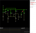
1719646481697.png

It worked great on the simulator, so I assumed it was fine and I designed a small PCB board. I had some space constraints so I needed to use small transistors (AO3401) and FET (S9014-J6):
1719646558041.png


Problem is it doesn't seem to work at all after I made the board, when I press the button nothing happens. Charge controller and BMS seem to function, but when I press the button LED3 and Fan won't turn ON.
I tried switching C4 to 10uF since it seemed to work much better at least in the simulator, but it didn't make any difference in real life, still nothing.

Do you guys have any idea what could be going on here? I'm not interested in changing completely the design for a microcontroller or something radically different, in my opinion this circuit should be relatively close to working but surely there's a mistake somewhere I just can't see it.
Thanks a lot in advance for your answers
 

LowQCab

Joined Nov 6, 2012
4,346
This project could be far less complex, and therefore have fewer points of failure.

I am assuming that You want a single "Push-On-Push-Off" Push-Button,
and not 2 separate On and Off Buttons.

You didn't specify how much Current Your Fan needs.
The Circuit below will sink a maximum of ~100mA,
if your Fan demands more Current than that,
You will need to add a single MOSFET Transistor on the Output.

The Schematic below shows a ~12-Volt Power-Supply, but it will work just fine on ~3-Volts.
Check you Specification-Sheets to make sure that your FET will fully turn-On with only ~3-Volts.

The Transistor number S9014-J6 is a BJT-Transistor, not a MOSFET, as depicted in your Schematic.


I would recommend a CMOS 7555 to replace the old 555 shown in the Schematic below, either will work.

A 100nF Power-Supply-Bypass-Capacitor is not shown, but is required for ANY and ALL Chips.
( from Pin-1 to Pin-8 )
.
.
.
555 Push-Button Switch .png.
 

Thread Starter

Forcerouge

Joined Jun 29, 2024
14
Thank you for your reply LowQCab,
Actually I was aware I could use a 555, but I wanted to do a "proper" circuit with basic components, in order to better understand how all of this works. I'd really like to make it work without having to resort to this kind of IC. Maybe its a bit dumb, but I did learn a ton of stuff while designing this circuit.

I think I even understand fully how it is supposed to work, which is why I'm confused because I can't find any obvious error in my schematic.

But your message pointed out the fact that it could be my choice of components. I thought I chose a mosfet, I'm not sure what happened there maybe I mixed up something while ordering components...
So I'm going to just try replacing this component with a FET, as it is likely the culprit.

Thank you again for pointing me in the right direction. If you spot anything weird or if you have any advice for a suitable mosfet don't hesitate to tell me!


If I really fail at making this circuit work then I guess I guess my plan be will be the 555. The fan requires 150mA.
Have a great weekend,
 

Thread Starter

Forcerouge

Joined Jun 29, 2024
14
Here is a screen capture from an EEVBLOG video, a bit simpler and better circuit.
Below is the LTspice sim of a version of the circuit that uses only one NPN in addition to the P-MOSFET:
Thanks guys,
Yeah I've checked google before making my circuit and also after it didn't work. Came across both of these designs and they werent working for me, but I can't recall why.
The thing is, I was searching for advices about the circuit I already have, because I already got the PCB done so I'd like to make it work instead of having to make another one. I could cut a few traces, make some bridges, etc. I just don't want to start another gamble on another circuit, this one is already the second one I tried. First one was able to ON, but not OFF (using this schematic).
 

LowQCab

Joined Nov 6, 2012
4,346
This is why You make the PCB the very last step.

The Circuit needs to be verified as completely operational,
and then thoroughly abused in every way imaginable,
before adding the additional complexities of an actual
dedicated PCB that can be mass-produced if that's where You think the project is ultimately going to go.

Most of the time, on simpler Circuits, I won't even bother with a proper PCB, ever.
A "Vero-Board", AKA, "Through-Hole-Boards", and about ~75 other names for
a PCB-Board with Copper-Plated-Holes laid-out in a "Grid-Pattern" covering the whole Board,
will do just fine in a "permanent" application,
as long as You develop good layout-design and implementation practices.
This can be done initially with "Grid-Paper" and a Pencil, or with a Computer-Drawing-Program.
I am still using the ~25-year-old ancient-relic "Microsoft-Picture-It" for Schematics, and simple Grid-Layouts,
but I use "ExpressPCB-Plus" to make complex Multi-Layer-PCBs when actually needed, because
it uses the exact dimensions of popular Through-Hole-Component-Packages, and SMD-Packages.

I would recommend that You check-out "SchmartBoards"
instead of creating a proper PCB for simple projects.
They even have Boards that are specifically designed for use with SMD Components.
.
.
.
Example PCB .png
.
 
Last edited:

crutschow

Joined Mar 14, 2008
34,910
I already got the PCB done
That's why you always breadboard a circuit before making the PCB (unless, of course, you don't mind spending money on a PCB that may not work).
A simulation is not a guarantee that the circuit will work in practice, only an indication that it may.
 
Last edited:

Thread Starter

Forcerouge

Joined Jun 29, 2024
14
I verified that it could work as much as I could. As you can see in my first post, I simulated the circuit, then I modeled it in an EDA software (EasyEDA), and then only I sent it to production.
I don't see what else I could have done, these components are very small its not like they would fit on a breadboard.
 

djsfantasi

Joined Apr 11, 2010
9,189
I verified that it could work as much as I could. As you can see in my first post, I simulated the circuit, then I modeled it in an EDA software (EasyEDA), and then only I sent it to production.
I don't see what else I could have done, these components are very small its not like they would fit on a breadboard.
There are many SMD Adapters that you can use to breadboard a circuit.
 

Thread Starter

Forcerouge

Joined Jun 29, 2024
14
As LowQCab pointed out, you have MOSFET's where there should be NPN transistors, and an NPN where the MOSFET should be. Is this just a marking error?
OMG I think you are right, I just inverted the markings in my EDA software and then I surely reported this mistake when placing the components!
I didn't realise both were wrong, I thought I just made a mistake on the fet when ordering the components....

Thanks a lot, I think that might be it!
I'll reflow another board and let you know how it went, thanks again!
 

crutschow

Joined Mar 14, 2008
34,910
these components are very small its not like they would fit on a breadboard.
You don't have to use SMD parts for the passive devices (resistors, capacitors) for the breadboard, you can use the equivalent through hole devices.
There may also be through-hole equivalents for the active parts.
 

crutschow

Joined Mar 14, 2008
34,910
For reliably switching in my LTspice sim, I had to increase C4 in your circuit to at least 20µF.

Why did you reduce it from 10µF in your sim (marginally doesn't work in my sim) to only 270nF in your schematic?

1719761267337.png________1719761377370.png
 
Last edited:

Thread Starter

Forcerouge

Joined Jun 29, 2024
14
As LowQCab pointed out, you have MOSFET's where there should be NPN transistors, and an NPN where the MOSFET should be. Is this just a marking error?
That was the issue, I just swapped the transistors and Mosfets and now it works!
Awesome! :cool:

Thanks again !

For reliably switching in my LTspice sim, I had to increase C4 in your circuit to at least 20µF.
Yes you are right,
The switch isn't stable when trying to turn it OFF, I'll try 10uF then 20 if it's not enough


Why did you reduce it from 10µF in your sim (marginal in my sim) to only 270nF in your schematic?
________
The original design I found on internet was using 270nF.
When I experimented in the simulator it didn't work well with this value, so I increased it to 10uF which seemed to work the best.
Then when I drew the final layout in the EDA software I decided to trust the original design and so that's how the 270nF ended there.

Nicely spotted, thanks for your great help as well!
 

crutschow

Joined Mar 14, 2008
34,910
The switch isn't stable when trying to turn it OFF, I'll try 10uF then 20 if it's not enough
There's no down side to using a larger capacitor to add margin.
Going to 100µF should be fine.
You don't want a marginal circuit that may fail down-the-road at a different ambient temperature, or when parts change value with aging (particularly electrolytic caps).
I decided to trust the original design and so that's how the 270nF ended there.
If a sim tells you the circuit works, then there's a good chance it will with real parts.
If a sim tells you it won't work or is marginal, then there's a high chance that it won't work with real parts.

Circuits you find on-line are often not simulated or well tested.
Some flat-out will not work (apparently paper designs only).
So consider that the next time you use one.
 

LowQCab

Joined Nov 6, 2012
4,346
The Falstad-Simulator can be a useful tool, especially for those people who are just starting-out,
but it quickly looses value because of not providing Graphical-Displays of Voltage and Current,
both of which can reveal a huge amount of very important information.

That must be the biggest, and most complex Push-Button-Circuit that I've ever seen.
.
.
.
 

Thread Starter

Forcerouge

Joined Jun 29, 2024
14
The Falstad-Simulator can be a useful tool, especially for those people who are just starting-out,
but it quickly looses value because of not providing Graphical-Displays of Voltage and Current,
both of which can reveal a huge amount of very important information.

That must be the biggest, and most complex Push-Button-Circuit that I've ever seen.
I'm not sure why you are saying this, it does provide a very intuitive way of seing voltage and current.
Voltage is shown by a color gradient from red to green, and current is shown by the speed of the moving little dots. You can get the exact voltages and current values just by clicking on any part of the circuit you like, you can even set voltmeters and scopes anywhere to see what's going on.

I can't tell if this is a complicated circuit as I don't have much experience. I tried some simpler version before with only one transistor and it was only able to switch ON then latch permanently, I wasn't able to switch the load OFF. Many designs over the internet just don't seem to work at all, it wasn't easy to find one that did. This one works no matter what kind of load is powered (capacitive, resistive or inductive).
Also I don't find it so complicated now that I've undertood how it works, it's pretty clever.
 

Thread Starter

Forcerouge

Joined Jun 29, 2024
14
There's no down side to using a larger capacitor to add margin.
Going to 100µF should be fine.
I tried many values in the simulation and the downside I found with a value too high was that it would need too long for the capacitor to charge, which means that a longer rest time is needed between two button press.
With 100uF the button needs about two seconds to reset between two consecutive press. It's a bit too long for my liking, the optimal value during my attempts was around 10uF.
But I'll check in real life and adjust according to reality.
 
Top