 Facebook
 Google
 GitHub
 Linkedin
am also trying to do a similar idea that I can not figure out. I would like to install indicator light on my kato turnouts. I would like the green light on the track that’s open and a red light on the one that is not. They are a signal coil that only uses momentary power to move the turnout. Reversing polarity moves it back. Can this be done some how ? They are twined together so I am using 18 volts dc with a dual button board.
 Stuck here because I can’t figure out how to get lights to stay on with momentary power only
Stuck here because I can’t figure out how to get lights to stay on with momentary power onlyAttachments
-
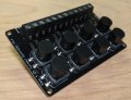 280.1 KB Views: 6


