Minimum Current Requirements for an Arduino Nano 33 BLE analoge input.

Thread Starter

MB107

Joined Jul 24, 2016
400


Most have 2 you'll only using one pin 2 and 3 output on 1 and the power pins the lm 358 easy one two play with. There more better ones as you learn but these are used a lot with microcontollers
Are you recommending I use the op amp or leave it out. For the moment I'm considering leaving it out because I don't understand it and it does work fine. That could change as soon as I install this into a car. Also is there any chance that these are already built into the Arduino input pins?

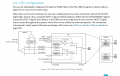
Narrowing the LM 358 down to through hole versions that are in stock gives me 5 options. All the parameters are yet to be understood.

1732024935641.png
 

Thread Starter

MB107

Joined Jul 24, 2016
400
Take a look at these two images from the ATmega328 datasheet for optimizing the ADC.

The first image shows there is a fairly large series resistor connected to the timing capacitor mentioned by be80be. This means you can directly connect a (low impedance) voltage source to the ADC input without damaging it. Since you are using a voltage divider, find a combination that equals no more than 10kΩ (product over sum formula). The opamp circuit you posted provides a low impendence output but isn't really needed in this situation.

View attachment 336190

The second image is a bit off topic but relevant. By default, the ATmega328 compares the ADC input to the onboard 5V regulator which is prone to noise. A better option is to use the onboard 1.1V voltage reference which is much more stable. All you need to do is add the line "analogReference(INTERNAL)" to your code and change any ADC calculations from 5V to 1.1V. This has the added benefit of improving the quantization level from (5V / 1024 = 5mV) to (1.1V / 1024 = 1mV) so you'll get more precise readings.

https://www.arduino.cc/reference/tr/language/functions/analog-io/analogreference/

View attachment 336191
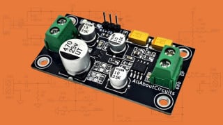
Thanks for the reply. I'm not using the ATmega328. The Nano 33 BLE Rev2 uses a Nordic nRF52840. I believe the equivalent section of the Nordic data sheet is partially here on page 149, but its all stuff I am not familiar with. I have also posted links to the Arduino Nano 33 BLE as well as the Nordic data sheet. Interesting that the picture shows 2 op amps?

1732026142134.png

https://store-usa.arduino.cc/produc...77327&pr_ref_pid=7296997556431&pr_seq=uniform

https://content.arduino.cc/assets/Nano_BLE_MCU-nRF52840_PS_v1.1.pdf
 

Thread Starter

MB107

Joined Jul 24, 2016
400
The source resistance seen by the ADC input is NOT the sum of the two resistor values in the potential divider. It is the two resistors in parallel. so 3.3K and 33 K in parallel would be be seen a a source resistance of 3K.
The load on the battery would look like a 36.3K resistor so it would be 12/36.3K = 0.33 mA

Les.
Exactly
 

Thread Starter

MB107

Joined Jul 24, 2016
400
If you are only displaying the output on 3 LEDs you would not need any great accuracy. If you do require more accuracy than a 10 bit ADC you could considder using an INA219 which has a 12 bit ADC. It will also measure your 12 -14 volts directly without a potential divider. It can also measure the current on the positive of your 12 - 14 volts.
I have uses a number of these for remote moitoring of 12 volt battery charging together with a PIC12F1840 micro and an HC12 for the wireless data link.
Les.
See post 19. I am currently using 10 bit ADC but the Nano33 BLE is capable of 12 bit ADC just by changing mu analogRead() statements to analogReadResolution(). I really only need about 0.1V resolution on this. I can also increase my resolution by using more of the input pins voltage range by increasing the resistance of the lower 3.3K resistor to about 7K. I have a transorb that will clip the max input voltage to 16V so I can use a 7K resistor safely.
 

Thread Starter

MB107

Joined Jul 24, 2016
400
The voltage divider still draws current. I calculated R1=11k, R2=110k provides the highest series resistance of 121k while not exceeding the stated 10k maximum equivalent resistance (output impedance). I don't think there is a better combination that yields no less than 121k Rs and no more than 10k Req.
OK but the 10KΩ came from post #13 which was based on the ATmega328 chip. Any thoughts on the Nordic nRF52840 chip mentioned in post #22. The way I did this originally was to size it based on maximum current available to the input pin, which is 10ma. See DC Current per IO pin? Using 15V for real automotive voltage it should be somewhere > 1500Ω so I assume that is the lower end. But I'm still not convinced 10MΩ is the upper end for the Nordic nRF52840.

1732030168755.png
 
OK but the 10KΩ came from post #13 which was based on the ATmega328 chip. Any thoughts on the Nordic nRF52840 chip mentioned in post #22. The way I did this originally was to size it based on maximum current available to the input pin, which is 10ma. See DC Current per IO pin? Using 15V for real automotive voltage it should be somewhere > 1500Ω so I assume that is the lower end. But I'm still not convinced 10MΩ is the upper end for the Nordic nRF52840.

View attachment 336222
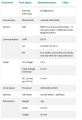
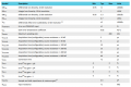
I found this chart on page 397 of the datasheet. It states the max source resistance for the chosen acquisition time. Since you are sampling 0Hz DC, I think you can get away with the maximum acquisition time of 40us with a 800k source resistance.

Given you want a 10:1 voltage divider with minimal current draw:

Rs = (R2 / R1) / (R2 + R1)
Rs = (8.8M / 880k) / (8.8M + 880k) = 800k

The current draw on the battery will be:

14V / 800k = 16uA / 222uW

This is a lot less than the self-discharge of a car battery so I don't think you'll have to worry about the voltage divider draining the battery over time. There is also no apparent need to push it to the limits.. I'd go with Rs = 400k (4.4M and 440k) for a 40us acquisition time. This leaves a lot of headroom for the internal circuitry to function properly while adding in some noise immunity and reducing the settling time.

As for adding an op-amp, it could of benefit if you want to reduce the acquisition time while keeping a large source resistance on the voltage divider. Another benefit could be an active low pass filter for noise immunity. I don't see these being very useful in your situation though.

I should add that I haven't used your microcontroller nor am I an expert. Hopefully someone can confirm these findings.

saadc.png

https://files.seeedstudio.com/wiki/XIAO-BLE/Nano_BLE_MCU-nRF52840_PS_v1.1.pdf
 

Thread Starter

MB107

Joined Jul 24, 2016
400
I found this chart on page 397 of the datasheet. It states the max source resistance for the chosen acquisition time. Since you are sampling 0Hz DC, I think you can get away with the maximum acquisition time of 40us with a 800k source resistance.

Given you want a 10:1 voltage divider with minimal current draw:

Rs = (R2 / R1) / (R2 + R1)
Rs = (8.8M / 880k) / (8.8M + 880k) = 800k

The current draw on the battery will be:

14V / 800k = 16uA / 222uW

This is a lot less than the self-discharge of a car battery so I don't think you'll have to worry about the voltage divider draining the battery over time. There is also no apparent need to push it to the limits.. I'd go with Rs = 400k (4.4M and 440k) for a 40us acquisition time. This leaves a lot of headroom for the internal circuitry to function properly while adding in some noise immunity and reducing the settling time.

As for adding an op-amp, it could of benefit if you want to reduce the acquisition time while keeping a large source resistance on the voltage divider. Another benefit could be an active low pass filter for noise immunity. I don't see these being very useful in your situation though.

I should add that I haven't used your microcontroller nor am I an expert. Hopefully someone can confirm these findings.

View attachment 336238

https://files.seeedstudio.com/wiki/XIAO-BLE/Nano_BLE_MCU-nRF52840_PS_v1.1.pdf
Sounds good. I will probably test it at 800K and if that works OK, I will run at 400K.

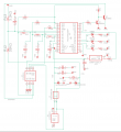
I have also updated the sketch to show the trim pot I wanted to install. Based on our conversations It appears that I will need some minimum resistor, I put it in as R14 since the pot can be at zero in some cases. I have it in as a 10K resistor and it will work with a 10K pot. But it sounds like I can use a 400K pot with a 400K resistor. The trim pot is something I haven't tried at all yet.

I don't have any of these high ohm resistors, so it may take me a while to close the loop on this.

Thank You for taking the time to pour through the data sheet.

1732045825325.png
 
Sounds good. I will probably test it at 800K and if that works OK, I will run at 400K.

I have also updated the sketch to show the trim pot I wanted to install. Based on our conversations It appears that I will need some minimum resistor, I put it in as R14 since the pot can be at zero in some cases. I have it in as a 10K resistor and it will work with a 10K pot. But it sounds like I can use a 400K pot with a 400K resistor. The trim pot is something I haven't tried at all yet.

I don't have any of these high ohm resistors, so it may take me a while to close the loop on this.

Thank You for taking the time to pour through the data sheet.

View attachment 336240
The table I posted lists Rinput = >1M so the trimpot wiper should be able to go from 3.3V to GND without a series resistor.

Also, what is the nature of the fan? I see you have the input to the pot coming from D8 going into A7 but I'm not sure why. You said:

"The trim pot I want to add will be used to control the fan run time after the engine is shut off. For example control voltage from 0-3.3V using the trim pot and reading the voltage at an analog input pin. 0V and the fan does not run after engine off. 3.3V and the engine runs for 60 second."

If this is the case, the pot should be connected directly to +3.3V. Then you map the quantization levels to time programmatically. Something like this for a 10 bit ADC:

0 -> 0s
255 ->15s
511 -> 30s
767 -> 45s
1023 -> 60s

You can do this manually with conditional statements or use the map() function. The code below maps the 1024 quantization levels of a 10 bit ADC to 60 units. Then use fanTime in your timing function.

C:
void setup() {}
void loop() {
    int fanTime = analogRead(7);
    fanTime = map(val, 0, 1023, 0, 59);
}
 

Thread Starter

MB107

Joined Jul 24, 2016
400
The table I posted lists Rinput = >1M so the trimpot wiper should be able to go from 3.3V to GND without a series resistor.

Also, what is the nature of the fan? I see you have the input to the pot coming from D8 going into A7 but I'm not sure why. You said:

"The trim pot I want to add will be used to control the fan run time after the engine is shut off. For example control voltage from 0-3.3V using the trim pot and reading the voltage at an analog input pin. 0V and the fan does not run after engine off. 3.3V and the engine runs for 60 second."

If this is the case, the pot should be connected directly to +3.3V. Then you map the quantization levels to time programmatically. Something like this for a 10 bit ADC:

0 -> 0s
255 ->15s
511 -> 30s
767 -> 45s
1023 -> 60s

You can do this manually with conditional statements or use the map() function. The code below maps the 1024 quantization levels of a 10 bit ADC to 60 units. Then use fanTime in your timing function.

C:
void setup() {}
void loop() {
    int fanTime = analogRead(7);
    fanTime = map(val, 0, 1023, 0, 59);
}
Originally I was going to connect it to the 3.3V bus. But since its only used the first time the engine starts, I figured I would put it on a pin that I can turn on and off. Therefore D8.

The trim pot sets the fan to run for some time after the fan is turned off anywhere between 0 and 60 seconds. D8 gets turned on high during the setup. An anologRead is performed to read the trim pot setting and D8 gets set low. This value only gets used when the engine gets shut down. So I grab the value once during the setup. At this time I do not have a trim pot and I just use a constant set at 30 seconds. So the trim pot just makes it user adjustable.

It will be something more like. But if I don't need a resistor I can use the map.

void setup() {
pinMode(A7 INPUT);
pinMode(D8 OUTPUT);
digitalWrite(D8, high);
int FanPostRunTime = analogRead(A7);
FanPostRunTime = FanPostRunTime*SomeMultiplier;
digitalWrite(D8,low);

void loop() {
Everything else to run the fan.
}
 
Originally I was going to connect it to the 3.3V bus. But since its only used the first time the engine starts, I figured I would put it on a pin that I can turn on and off. Therefore D8.

The trim pot sets the fan to run for some time after the fan is turned off anywhere between 0 and 60 seconds. D8 gets turned on high during the setup. An anologRead is performed to read the trim pot setting and D8 gets set low. This value only gets used when the engine gets shut down. So I grab the value once during the setup. At this time I do not have a trim pot and I just use a constant set at 30 seconds. So the trim pot just makes it user adjustable.

It will be something more like. But if I don't need a resistor I can use the map.

void setup() {
pinMode(A7 INPUT);
pinMode(D8 OUTPUT);
digitalWrite(D8, high);
int FanPostRunTime = analogRead(A7);
FanPostRunTime = FanPostRunTime*SomeMultiplier;
digitalWrite(D8,low);

void loop() {
Everything else to run the fan.
}
You could set the fan time by pressing a button.

1 press -> 10s
3 presses -> 30s
6 presses -> 60s

Then something like 1 long press to save a preset value. Might work out better because you don't have to look at the trimpot to see where it's set.
 

Thread Starter

MB107

Joined Jul 24, 2016
400
You could set the fan time by pressing a button.

1 press -> 10s
3 presses -> 30s
6 presses -> 60s

Then something like 1 long press to save a preset value. Might work out better because you don't have to look at the trimpot to see where it's set.
Not really any need. With a 1 turn trim pot its just 0 turn = 0sec, 1/2 turn = 30sec, full turn = 60sec. Nothing about this needs to be exact and it a 1 time setup. Buttons or trim pots, in my case this controller is so buried, weather I use a constant written in code, a trim pot or buttons, the controller needs to be removed from under the dash to do the programing or trim pot or button setting.

Still don't understand why I don't need to increase the resistance for the input pin A7 like we discussed for the voltage sensing pin A0.
 
Not really any need. With a 1 turn trim pot its just 0 turn = 0sec, 1/2 turn = 30sec, full turn = 60sec. Nothing about this needs to be exact and it a 1 time setup. Buttons or trim pots, in my case this controller is so buried, weather I use a constant written in code, a trim pot or buttons, the controller needs to be removed from under the dash to do the programing or trim pot or button setting.

Still don't understand why I don't need to increase the resistance for the input pin A7 like we discussed for the voltage sensing pin A0.
The ADC pins are protected by a >1M resistor shown in the table. Additional resistance on either side of leg will limit the range because it wont span the full 1024 bits.

As long as you don't exceed 3.3V at the input you should be fine. The digital pins need to be current limited because they have push-pull connections to 3.3V and GND.
 

Thread Starter

MB107

Joined Jul 24, 2016
400
The ADC pins are protected by a >1M resistor shown in the table. Additional resistance on either side of leg will limit the range because it wont span the full 1024 bits.

As long as you don't exceed 3.3V at the input you should be fine. The digital pins need to be current limited because they have push-pull connections to 3.3V and GND.
Well everything worked out perfectly. For the voltage sensing resistors I twisted 8 1MΩ resistors together and ran it with another 1MΩ. That put RS a close to 900KΩ but it worked fine. So I will do something to keep it closer to 400KΩ.

The trim pot works perfectly fine without a resistor. I used a 500K trim pot only because I had it lying around. Any suggestions for sizing on that?
 
Well everything worked out perfectly. For the voltage sensing resistors I twisted 8 1MΩ resistors together and ran it with another 1MΩ. That put RS a close to 900KΩ but it worked fine. So I will do something to keep it closer to 400KΩ.

The trim pot works perfectly fine without a resistor. I used a 500K trim pot only because I had it lying around. Any suggestions for sizing on that?
I think the value for the fan trimpot will have the same upper limit of 800k for 40us acquisition time. That way the worst case scenario doesn't exceed the maximum source resistance of 800k. The 500k trimpot you have leaves a large margin and draws very little passive current. Any more resistance is negligible. Have you measured the power consumption of your setup?
 

Thread Starter

MB107

Joined Jul 24, 2016
400
I think the value for the fan trimpot will have the same upper limit of 800k for 40us acquisition time. That way the worst case scenario doesn't exceed the maximum source resistance of 800k. The 500k trimpot you have leaves a large margin and draws very little passive current. Any more resistance is negligible. Have you measured the power consumption of your setup?
Thanks for your help. The larger resistors brought it down ~ 0.35ma. I also shut off the UART which brought it down another .5ma. I'm currently running at about 8ma with the Arduino in delay() mode. I am still investigating ways to put the Arduino into sleep mode.
 
Top