Microphone amplifier Circuit op amp Amplifying

Thread Starter

Jeffery Vahrenkamp

Joined Jun 16, 2016
53
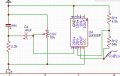
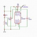
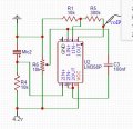
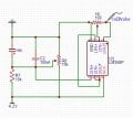
I am trying to build a small microphone amplifier for an electret microphone. I am using an LM358P duel op amp IC to amplify the signal. From my understanding of the design, the first op amp is used to boost the current in a voltage follower configuration. I then use a capacitor to off set a slight DC bias of 80mv. I use a pot as a voltage divider make my voltage in an ideal range for my ADC. I then use the second op amp to amplify the signal with another pot (Design 1). I didn't really see much of an amplification. If my understanding is right, with a 10k pot, I should be able to get from 0 - 10k ( or the op amp max) voltage amplification. However when I adjust the second pot, I see no change in amplification. I tried manually setting the amplification to 30x with a 47k and 1.5k resistor (i have it marked 300k and 10k in the diagram 2). The signal stayed the same, though the signal got a little noisier. Last thing I tried was to switch the order of the bias removal, just incase I needed the signal in the middle of the op amp range before passing it to the voltage follower (diagram 3). No Joy.

My gut says something is wrong with my op amp ic, but I'm not sure how to test it. Setting up a voltage follower on both op amps works fine, but neither seems to amplify.
 

Attachments

danadak

Joined Mar 10, 2018
4,057
For starters you have the input OpAmp biased as high as its supply V,
but its CM range in is limited to Vsupply - 1.5. And the bias point
should be fixed in a single supply application, in your case (4.2 - 1.5)/2 = ~
1.35V. This is circuit 1 & 2. In 3 your pot varies the offset.

In any event electrets want to operate into very high impedance, and your
input circuitry to the follower is all low Z. Here is a good input circuit -


http://mynixworld.info/2017/09/01/simple-electret-microphone-circuit/


You would be better off using a RRIO OpAmp, in general.


http://www.ti.com/lit/ug/tidu765/tidu765.pdf

https://wiki.analog.com/university/courses/engineering_discovery/lab_4/theory


Regards, Dana.
 

Thread Starter

Jeffery Vahrenkamp

Joined Jun 16, 2016
53
Hi Dana

I modified the circuit a little with what you said in mind. I lowered the voltage from the voltage divider to 1v and 0.5v. I also put a 0.44uF capacitor on the output of the microphone. Nothing really changed. I also reduced the resistor value for the microphone to ground, which did increase the peak to peak voltage.
 

Attachments

Thread Starter

Jeffery Vahrenkamp

Joined Jun 16, 2016
53
I have sold 150,000 of these FM bugs and you can hear a pin drop and the FM sound is so clear that you think the person is in the next room
That was super helpful. The explanation on that website was very helpful. That spy bug is about what I was looking to build, though I want to use an ADC to send the sound over wifi. Just to make sure I am following the circuit. Would I adjust the 10k and 1M resistors to get the center point of my ADC range? Or would I just pass the signal through the 100 nf cap and add my offset voltage to the other side?
 

Attachments

Last edited:

Colin55

Joined Aug 27, 2015
519
Whatever type of circuit you pass the output of the single transistor amplifying stage into, will attenuate the signal and you cannot make any decisions until you see what the signal looks like.
 

Audioguru

Joined Dec 20, 2007
11,248
An electret mic draws a current of about 0.5mA and needs at least 2V across it. Look at the spec's for the 730 electret mics in Digikey.
Colin's mic in his preamp transistor circuit has only 0.2V across it because the 68k resistor feeding it should be 10k ohms when the supply is 9V. If a fully charged Lithium battery powers the transistor circuit with 4.2V then the resistor powering the mic should be about 3.3k ohms so that the mic still works when the battery voltage drops to 3.3V.
 

Colin55

Joined Aug 27, 2015
519
Audioguru has absolutely no idea what he is talking about. I have sold 50,000 of these kits and the microphones I buy at 20,000 at a time are very sensitive and any resistance lower than 68k for 9v will overload them and create distortion.
It's best for people who don't know what they are talking about, to keep their ideas to themselves.
 

Audioguru

Joined Dec 20, 2007
11,248
The spec's for an electret mic says its minimum voltage is 2V for almost all normal ones, not 0.2V. They produce distortion when they have less than about 2V across them.
Colin, maybe your electret mics are not normal ones. Please post its detailed datasheet showing its current and its recommended voltage.

Your FM transmitter kit is missing pre-emphasis so it will sound muffled on an FM radio, not sound clear, because all FM radios have matching de-emphasis. Lookup pre-emphasis and de-emphasis in Google.
Your FM transmitter RF frequency will change as the battery voltage runs down because it is missing a voltage regulator.
Your FM transmitter radio frequency will also change when something moves towards or away from its antenna because its antenna is connected directly to its LC tuned circuit because it is missing an RF buffer output transistor.
My FM transmitter circuit does not have those problems that yours has.
 

Attachments

Top