Microcontroller powered from the battery gives reverse voltage through UART to FT232RL chip

Thread Starter

venkat9

Joined Sep 21, 2020
14
Hi,
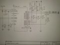
i have powered my microcontroller from the battery. and have connected the Microcontroller UART connected to FT232RL converter.
Now the problem is, when the MCU is powered, the UART voltages come in to the FT232RL resulting in the damage of FT232RL chip.
can you please advise on how to fix this issue?

Regards,
Venkatesh
 

Papabravo

Joined Feb 24, 2006
21,159
What you are saying makes no sense. What does "reverse voltage through UART" even mean. Could you possibly be more precise?
 

Thread Starter

venkat9

Joined Sep 21, 2020
14
What you are saying makes no sense. What does "reverse voltage through UART" even mean. Could you possibly be more precise?
i have connected FT232RL (USB- Serial transceiver ) which is connected to the microcontroller UART. am independently powering my Microcontroller with battery. thus the voltage from the UART connection of microcontroller comes in to the FT232RL chip, thus damaging the FT232RL chip.
 

Papabravo

Joined Feb 24, 2006
21,159
i have connected FT232RL (USB- Serial transceiver ) which is connected to the microcontroller UART. am independently powering my Microcontroller with battery. thus the voltage from the UART connection of microcontroller comes in to the FT232RL chip, thus damaging the FT232RL chip.
I think it is time for a schematic because your verbal descriptions descriptions don't convey much useful information.
How is the FT232RL powered when you connect the microcontroller to the battery?
 

Thread Starter

venkat9

Joined Sep 21, 2020
14
is time for a schematic because your verbal descriptions descriptions don't convey much useful information.
How is the FT232RL powered when you connect the microcontroller to the battery?
Microcontroller is powered with battery. microcontroller UART which is connected to FT232RL gives voltage to FT232RL thus giving un wanted voltages and damaging the FT232RL
 

Thread Starter

venkat9

Joined Sep 21, 2020
14
Is the FT232RL a 3.3V device and you're feeding it 5V signals?
FT232RL is a USB to serial IC. so it can take 5V. but problem is that external microcontroller UART that is connected to this chip is giving the voltage to chip, resulting in the damage of the chip.
 

sagor

Joined Mar 10, 2019
903
Need a schematic. Even if you draw it on paper and take a picture, would make it easier to understand how things are connected, including UART, power supplies, voltages, etc.
 

upand_at_them

Joined May 15, 2010
940
but problem is that external microcontroller UART that is connected to this chip is giving the voltage to chip, resulting in the damage of the chip.
What does "external microcontroller UART" mean? Is it the UART within the microcontroller? Or a separate chip, like a MAX232?

What does "giving voltage to the chip" mean? It's providing the power supply? What voltage are you operating the micro at? What are the UART output levels?...That's in the datasheet. And what are the acceptable input levels to the FT232?
 

Ian0

Joined Aug 7, 2020
9,674
What micro controller?
The typical PicMicro has a RS22 module built in.
Max.
Do you mean RS232?
If so, then it DOESN'T have an RS232 module built in. It has a UART. RS232 defines the output voltages at bethe same number as Euros as Pounds.tween +3V and +25V for a logic zero, and -3V to -25V for a logic 1. The Pic can't do that. You need some sort of output driver to generate the required voltages, and the MAX232 can do that from a single +5V supply using a charge pump.
 

Ian0

Joined Aug 7, 2020
9,674
FT232RL is a USB to serial IC. so it can take 5V. but problem is that external microcontroller UART that is connected to this chip is giving the voltage to chip, resulting in the damage of the chip.
I think I understand. Your mcu is connected to a RS232 line driver, which you have connected to the FT232, so your are driving as much as +/-12V into the FT232 and it doesn't like it.
What you need is an RS232 line receiver to translate the levels back to 0V/5V, which you can then connect to the FT232. If you've only got the USB 5V supply, then the MAX232 will do the job.
Don't think you can cheapen out and clamp the signal with a resistor and a zener - don't forget that RS232 levels are upside down!
Alternatively, if you can bypass the RS232 line driver and get the signal directly from the mcu, you could use that.
 

Papabravo

Joined Feb 24, 2006
21,159
FT232RL is a USB to serial IC. so it can take 5V. but problem is that external microcontroller UART that is connected to this chip is giving the voltage to chip, resulting in the damage of the chip.
I think you have misinterpreted the situation and don't know what you are talking about. If the chips have been damaged then it is because you FAILED to read the datasheet and did something you should not have done.
 

Thread Starter

venkat9

Joined Sep 21, 2020
14
I think you have misinterpreted the situation and don't know what you are talking about. If the chips have been damaged then it is because you FAILED to read the datasheet and did something you should not have done.
USB to TTL (FT232RL), am preparing for the schematic, give me a minute. thankyou
 

Papabravo

Joined Feb 24, 2006
21,159
OK
Let's start by saying that this is a fragment of a schematic and conceals important details. You want help, but you are being an obfuscating obstructionist.
What is USB_PWR connected to?
Why is 3V3OUT connected to USB_PWR

If the STM32 has GPIO pins connected to TXD and RXD then they will be configured at power up as high-impedance inputs which can neither source nor sink current. IMHO this pretty much collapses your earlier conclusion. Even if USB_PWR is at 0 Volts DC I don't see what harm it will do.
 

Thread Starter

venkat9

Joined Sep 21, 2020
14
OK
Let's start by saying that this is a fragment of a schematic and conceals important details. You want help, but you are being an obfuscating obstructionist.
What is USB_PWR connected to?
Why is 3V3OUT connected to USB_PWR

If the STM32 has GPIO pins connected to TXD and RXD then they will be configured at power up as high-impedance inputs which can neither source nor sink current. IMHO this pretty much collapses your earlier conclusion. Even if USB_PWR is at 0 Volts DC I don't see what harm it will do.
USB_PWR is connected to rocker switch, that switches between usb power and battery power.
3V3OUT connected to get 3.3v internally generated from ic.
When am powering the circuit from the battery, txd and rxd are sending some data which is giving voltage to ft232rl thus making ds3 LED glow.
 
Top