 Facebook
 Google
 GitHub
 Linkedin
Hi everyone!
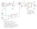
I'm making a custom board based on the ATSAMD21 MCU, which is also used in the Arudino Zero. I would like to incorporate a Micro USB connector, primarily for UART communication with a computer. I'll program the chip using Cortex debug with the Atmel ICE debugger, so the USB connection doesn't need to be used for that. I also would like to make use of the connection for 5V and 3.3V supply.
I've been looking at the schematic of Sparkfun's SAMD21 Dev Breakout Board, but cannot fully understand the schematic. I've attached relevant sections of the schematic. What is the purpose of the tri-state buffer? Is it so that setting USB_HOST_EN on/off somehow allows power to flow to the voltage regulator? I can't seem to understand how USB_ID and USB_HOST_ENABLE work together along with the buffer. Is this part even needed? If you get rid of it, does it mean that the board will always be on when plugged in?
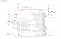
My second question is regarding USB_D+ and USB_D-. I understand the basics of what they are, but I'm not sure how to implement them. In the schematic, they are linked to specific pins on the MCU (PA24 and PA25). I'm assuming that these pins are somehow enabled to program the MCU via the on board debugger in the firmware. If I only want to use USB for UART, do I connect D- and D+ to the RX / TX pins used for UART, or is that over simplifying?
Thanks in advance for any guidance! I'm having trouble finding written documentation on how to connect USB on a custom board.
I'm making a custom board based on the ATSAMD21 MCU, which is also used in the Arudino Zero. I would like to incorporate a Micro USB connector, primarily for UART communication with a computer. I'll program the chip using Cortex debug with the Atmel ICE debugger, so the USB connection doesn't need to be used for that. I also would like to make use of the connection for 5V and 3.3V supply.
I've been looking at the schematic of Sparkfun's SAMD21 Dev Breakout Board, but cannot fully understand the schematic. I've attached relevant sections of the schematic. What is the purpose of the tri-state buffer? Is it so that setting USB_HOST_EN on/off somehow allows power to flow to the voltage regulator? I can't seem to understand how USB_ID and USB_HOST_ENABLE work together along with the buffer. Is this part even needed? If you get rid of it, does it mean that the board will always be on when plugged in?
My second question is regarding USB_D+ and USB_D-. I understand the basics of what they are, but I'm not sure how to implement them. In the schematic, they are linked to specific pins on the MCU (PA24 and PA25). I'm assuming that these pins are somehow enabled to program the MCU via the on board debugger in the firmware. If I only want to use USB for UART, do I connect D- and D+ to the RX / TX pins used for UART, or is that over simplifying?
Thanks in advance for any guidance! I'm having trouble finding written documentation on how to connect USB on a custom board.
Attachments
-
 33.1 KB Views: 4
 -
 44.5 KB Views: 3


