Micro FM Transmitter Help

Thread Starter

thompso

Joined Nov 21, 2010
7
Hi! Let it first be known that I have absolutely no training or real knowledge about circuitry or electronics. I'm hoping to get better at it, but I've never gotten any formal training and all that I've learned is from the internet. I'm pretty sure my soldering technique is wrong somehow.

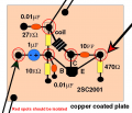
Now that that's over with, I need help on a little project I'm working on. For the past two weeks I've been trying to construct the micro FM transmitter from this website: http://anarchy.translocal.jp/radio/micro/howtosimplestTX.html

The website is a little hard to navigate, but it's all there. This transmitter was said to be a good beginner project, but I've run into some problems. Whenever I plug the 9v battery in, it starts to overheat. I'm not sure whether it's actually broadcasting anything since I've never left the battery in long enough to find the frequency it's transmitting at. I've built it twice and I've had the same problem both times.

I substituted the default transistor for the NTE123AP as the website suggests and shifted some things around to account for the different lead positions. The trimmer capacitor I use ranges from 5-25 pf. Aside from that, I've followed the picture quite faithfully. I've double checked with a multimeter that no solder is touching the ground where it shouldn't. One possible problem is that I've damaged the transistor while soldering. Would that cause the battery to overheat? I may have held the iron on the leads too long or held it too close to the plastic body.

Any help at all would be greatly appreciated!
 

Paulo540

Joined Nov 23, 2009
191
At first thought, it seems like the battery is getting shorted (or excessive current draw) somewhere.

Especially if nothing else is heating up that rapidly
 

Thread Starter

thompso

Joined Nov 21, 2010
7
Before I started soldering anything on, I used a multimeter to check that the elevated plates are isolated. It shouldn't be the source of the problem.

Edit: Come to think of it, there might be some invisible drips somewhere. Of course, now that everything is soldered together, the multimeter beeps wherever I put the leads. How do I test for a short in this case?
 

thatoneguy

Joined Feb 19, 2009
6,359
A meter in resistance mode shouldn't be putting out over 0.4V-ish so as not to forward bias semiconductor juntions, and only beep on 200Ω or less for continuity.

Does your meter have a diode check function? You should at least be able to verify the transistor appears as 2 diodes. (Base-Emitter for sure, Base-Collector is iffy with the 27k resistor)

The resistors other than the 470 ohm shouldn't set off a continuity beeper, the coil should show as a short. Use low resistance mode rather than "beep mode" to read the resistances.
 

Thread Starter

thompso

Joined Nov 21, 2010
7
I've fiddled around with this multimeter a bit and in continuity mode the only shorts I find are at the copper coil, where there should be one, and at the trimmer capacitor, where I don't know. In diode check mode, Base-Emitter shows as 0.268v and Base-Collector shows as 1.158v. In resistance mode, the 470 ohm resistor checks out, but both the other resistors show as 7.22k ohm. I don't know whether there's forward bias going on there or what. How do I know what the test voltage is? Can I change it?

Also, I failed to mention this before, but the trimmer capacitor I used has three leads. I looked around and can't seem to find a reason for that third one, so I just ignored it while soldering. Is it supposed to be a ground lead?

Also, I didn't solder in Manhattan style as I have no tweezers and have enough difficulty soldering anyway. Will that change anything?

Thanks so much for the help so far, guys.
 

thatoneguy

Joined Feb 19, 2009
6,359
Can you post a photo of your circuit as an attachment? Keep camera steady and focused so part numbers and any soldering issues can be identified.
 

Thread Starter

thompso

Joined Nov 21, 2010
7
I took some photos with my crappy iSight camera, but you can't tell **** from those. In a couple of hours, I'll have the time to take some proper photos with a proper camera.
 

Thread Starter

thompso

Joined Nov 21, 2010
7
Here are some pictures. A little fuzzy in some places, but anyone can just ask me for clarification. The joints are all visible. I think that's what needs checking.

Edit: Goodness, I forgot about image resolution. Now shrunk for your viewing pleasure.


Thread Starter

thompso

Joined Nov 21, 2010
7
Do you think that would be the source of the problem? If so, I'll work on my soldering technique and built this thing one more time. I only have two spare transistors left.

Thanks for all the help! I really appreciate it.
 

thatoneguy

Joined Feb 19, 2009
6,359
double check that none of the pads have a tiny accidental path to the ground plane, use your meter, no pads should show 0.00 ohms to ground.
 

Thread Starter

thompso

Joined Nov 21, 2010
7
Edit: Whoops, repeated a post.

I've checked that there are no accidental paths, at least that I can find. I'm just going to rebuild it one last time and if something still goes wrong, then I'll really need to look things over. This was supposed to be easy!
 

thatoneguy

Joined Feb 19, 2009
6,359
When soldering, make sure you heat up the entire "island" so the solder flows onto it instead of sitting on top as a little bubble. This should give better connections as well, some leads could be in the blob, but not perfectly connected (cold solder joint).
 

retched

Joined Dec 5, 2009
5,207
Using such a large plane, you are going to have to take your time soldering.

The ground plane WILL "wick" away the heat that you want to be concentrated at the solder pad and component lead.

Like thatoneguy said, heat that sucker. But remember to follow the datasheet for how long you can heat the part its self. You can heat the pad for a half hour if you want to, but as soon as you add the component, the clock starts ticking. You WILL damage your parts if you solder them too long.

This is one of those particular cases where a more powerful iron shines.

An adjustable iron is the best of all worlds because you can crank it up in cases like this, but dial down when doing ICs and finer pitched components with many leads.

If you have 40 pins to solder, you are going to be spending some time on the IC. The hotter the iron, the faster you will get done, but the more you will heat the IC. SO, if you dial down the iron, you can stay at or around the melting temp and take longer on the job.
 

radiohead

Joined May 28, 2009
514
Your circuit won't oscillate as it is. You need to put your trimmer cap in parallel with the coil, not connected to ground. That's probably why your transistor is overheating. Without the capacitor, you have no tank circuit. With no tank circuit, you have no colpitts oscillator. With no colpitts oscillator, you have no radio signal.

As for the soldering, just use a little paste flux and be sure your solder joint gets hot enough to weld the solder to the base metal. Don't let solder joints rest on the surface, they create a point of high resistance. Other than that, prettiness isn't critical, especially with Manhattan circuits.
 

thatoneguy

Joined Feb 19, 2009
6,359
Radiohead has a point. One lead of the cap is soldered to the ground plane. According to the diagram, it should be in series with the inductor and 470Ω resistor, directly across the C-E of the transistor.
 

radiohead

Joined May 28, 2009
514
Attached is the schematic for the drawing above. I found another flaw with the circuit layout above: the electrolytic capacitor is reversed. The positive end should be attached to the microphone, and the microphone will need a biasing resistor. Another solution (see attached circuit) would be to eliminate the electrolytic cap and connect the positive side of the microphone directly to the base of the transistor. Check your connections according to this schematic and you should have no problems.
 

Attachments

Top