Facebook
 Google
 GitHub
 Linkedin
I live where my water comes from my own well. Since the entire Western US is in a drought, I would like make a project to keep track of the static water level in my well as an indicator of the water table in our aquifer. When my well was drilled in 2005, the static water level was about 100ft.
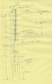
A crude drawing of my well is shown below. The well casing is 300ft long. The casing is 3"id Black ABS pipe. It is perforated with small holes all the way to the bottom. After the pump stops running, the water from the surrounding aquifer refills the casing so that the static level is even with the top of the water table.
The 1.5 h.p. pump is suspended 280ft down the bore, effectively hanging on 280ft of Sched 80 White PVC water (pressure) pipe, putting the pump about 20ft from the bottom of the bore. The pump is powered through a four-conductor rubber-covered cable with four #10AWG conductors.
Three of the conductors go to the motor windings (run winding & start winding, with one wire common to both windings) and the fourth wire is a (green) safety ground which is earthed at the top, and connects to the stainless steel body of the pump at the bottom.
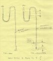
I tried lowering a #28AWG insulated wire (with a small stainless steel plumb-bob attached) thinking I could tell when the plumb-bob makes electrical contact with the standing water. Knowing the length of the wire would tell me where the static water level is. However, the pump cable meanders down the hole sort of loosely wrapped around the PVC water pipe, and what happened is that the wire and plumb-bob got jammed between the pump cable and the inside side-wall of the casing.
I am planning to get a coil of 3/8 PEX water pipe, and I will insert that down into the well. The PEX is stiff enough that I think it will push past the random coils of the pump cable, and strong enough that I could withdraw it from the well if I ever need to... I show the PEX pipe as the Standpipe on the drawing.
Here is what I am thinking. The PEX pipe comes premarked with length ticks. I can keep track of how much I have inserted down the casing. Imagine that I insert 90ft, and then apply very low air pressure at the top end. If the bottom end hasn't reached the static water level yet, there will be very little resistance (pressure rise) because the air can escape at the bottom. Now I keep pushing down more PEX, keeping track of the total length so far.
As the bottom of the PEX reaches the static water level, two things should happen. First, I should be able to hear bubbling as the air comes out around the now submerged end. Second, the air pressure required to keep air flowing will rise compared to prior to the end reaching the static level.
This establishes the static water level right now. Suppose I shove in another 33ft of PEX, and then secure it. That will put the open end of the PEX standpipe 33ft below the static water reference level.
Since 1 atmosphere of pressure (14.7 psi at sea level) will support a column height of 33ft of water, it should take about 14psi to push the water level inside the standpipe down to where the air starts bubbling. More over, if I slowly increase the air pressure inside the standpipe by bleeding it though an orfice, the air pressure will increase as the water column inside the standpipe is pushed down and then the pressure should stop increasing as the air begins bubbling around the open end of the standpipe.
So, as the static water level (aquifer level) fluctuates above and below the reference static level established above, it should be possible to measure the current static level by measuring the air pressure required to cause bubbling. Suppose in the future, the water table drops ten feet (I hope not). Now, the pressure required to bubble would be 14*(33-10)/33 psi, and it should be possible to calculate the new level just from the pressure measurement.
I would like to use an Arduino interfaced to a LCD, a gauge pressure sensor, and an electric pump. This is similar to measuring blood pressure. I have one of the inexpensive automated cuffs which I might be able to cannibalize for parts.
Help me here. What allowance do I need to make for my elevation (4316 ft MSL)? What allowance do I need to make for temperature? (The temperature 100ft underground is going to be constant, but do I need to know what it is)? The temperature of the water pumped from the well should be a good indicator.
Any other suggestions on alternative approaches welcome...
I have thought about echo location, measuring capacitance, etc, but none seems as clean as measuring air pressure....
A crude drawing of my well is shown below. The well casing is 300ft long. The casing is 3"id Black ABS pipe. It is perforated with small holes all the way to the bottom. After the pump stops running, the water from the surrounding aquifer refills the casing so that the static level is even with the top of the water table.
The 1.5 h.p. pump is suspended 280ft down the bore, effectively hanging on 280ft of Sched 80 White PVC water (pressure) pipe, putting the pump about 20ft from the bottom of the bore. The pump is powered through a four-conductor rubber-covered cable with four #10AWG conductors.
Three of the conductors go to the motor windings (run winding & start winding, with one wire common to both windings) and the fourth wire is a (green) safety ground which is earthed at the top, and connects to the stainless steel body of the pump at the bottom.
I tried lowering a #28AWG insulated wire (with a small stainless steel plumb-bob attached) thinking I could tell when the plumb-bob makes electrical contact with the standing water. Knowing the length of the wire would tell me where the static water level is. However, the pump cable meanders down the hole sort of loosely wrapped around the PVC water pipe, and what happened is that the wire and plumb-bob got jammed between the pump cable and the inside side-wall of the casing.
I am planning to get a coil of 3/8 PEX water pipe, and I will insert that down into the well. The PEX is stiff enough that I think it will push past the random coils of the pump cable, and strong enough that I could withdraw it from the well if I ever need to... I show the PEX pipe as the Standpipe on the drawing.
Here is what I am thinking. The PEX pipe comes premarked with length ticks. I can keep track of how much I have inserted down the casing. Imagine that I insert 90ft, and then apply very low air pressure at the top end. If the bottom end hasn't reached the static water level yet, there will be very little resistance (pressure rise) because the air can escape at the bottom. Now I keep pushing down more PEX, keeping track of the total length so far.
As the bottom of the PEX reaches the static water level, two things should happen. First, I should be able to hear bubbling as the air comes out around the now submerged end. Second, the air pressure required to keep air flowing will rise compared to prior to the end reaching the static level.
This establishes the static water level right now. Suppose I shove in another 33ft of PEX, and then secure it. That will put the open end of the PEX standpipe 33ft below the static water reference level.
Since 1 atmosphere of pressure (14.7 psi at sea level) will support a column height of 33ft of water, it should take about 14psi to push the water level inside the standpipe down to where the air starts bubbling. More over, if I slowly increase the air pressure inside the standpipe by bleeding it though an orfice, the air pressure will increase as the water column inside the standpipe is pushed down and then the pressure should stop increasing as the air begins bubbling around the open end of the standpipe.
So, as the static water level (aquifer level) fluctuates above and below the reference static level established above, it should be possible to measure the current static level by measuring the air pressure required to cause bubbling. Suppose in the future, the water table drops ten feet (I hope not). Now, the pressure required to bubble would be 14*(33-10)/33 psi, and it should be possible to calculate the new level just from the pressure measurement.
I would like to use an Arduino interfaced to a LCD, a gauge pressure sensor, and an electric pump. This is similar to measuring blood pressure. I have one of the inexpensive automated cuffs which I might be able to cannibalize for parts.
Help me here. What allowance do I need to make for my elevation (4316 ft MSL)? What allowance do I need to make for temperature? (The temperature 100ft underground is going to be constant, but do I need to know what it is)? The temperature of the water pumped from the well should be a good indicator.
Any other suggestions on alternative approaches welcome...
I have thought about echo location, measuring capacitance, etc, but none seems as clean as measuring air pressure....
Attachments
-
 843.9 KB Views: 104
Last edited:
 String/wire stuck between cables and drop pipe.