Hello all,
I wanted to get your thoughts on some techniques that might be used to measure noise and ripple on the output of a high voltage DC to DC converter.
Additional details:
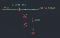
I searched around the internet and found that some people use an external AC coupler (looks to me like a high-pass filter) with a high-voltage capacitor in series with the HV line to block the DC from the output. Could I use a Cera-Mite 4700pF 6kV cap, and a 470 Ohm resistor to give me a cutoff of about 72kHz? This would block the DC voltage from the scope input while still allowing me to measure the ripple and noise, right? (granted that the noise frequencies would have to fall within what the filter allows). Would this method alter measurements and if yes, is there a way mathematically to compensate for that loss?
Am I on the right path or is there an easier way to achieve this? I have a few high voltage resistor-divider probes but it's hard to get a meter to pick up ripple in the mV/sub-mV range when voltages are divided down by 100 or 1000. What would you suggest?
I wanted to get your thoughts on some techniques that might be used to measure noise and ripple on the output of a high voltage DC to DC converter.
Additional details:
- DC to DC converter has variable output from 0v-4kV and the output is specified to 0.25mA max. This would be connected to a metal plate to hold it at that voltage potential. Switching Frequency range is 75kHz to 150kHz and ripple is specified to <0.1%
- DC to DC converter GND is common with earth ground, as is the oscilloscope.
- O-Scope (Tektronix TBS2204B) inputs rated for <= 350V
I searched around the internet and found that some people use an external AC coupler (looks to me like a high-pass filter) with a high-voltage capacitor in series with the HV line to block the DC from the output. Could I use a Cera-Mite 4700pF 6kV cap, and a 470 Ohm resistor to give me a cutoff of about 72kHz? This would block the DC voltage from the scope input while still allowing me to measure the ripple and noise, right? (granted that the noise frequencies would have to fall within what the filter allows). Would this method alter measurements and if yes, is there a way mathematically to compensate for that loss?
Am I on the right path or is there an easier way to achieve this? I have a few high voltage resistor-divider probes but it's hard to get a meter to pick up ripple in the mV/sub-mV range when voltages are divided down by 100 or 1000. What would you suggest?
Last edited: