 Facebook
 Google
 GitHub
 Linkedin
Hi everyone, I will try to be as descriptive as possible
Problem: Large coil not resonating at resonant frequency. I am trying to verify the calculated result of 281.2mH of large coil with oscilloscope.
What have I tried:
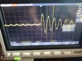
Measure resonant frequency of another small coil successfully. I will attach picture of my small coil resonating with 100n capacitor.
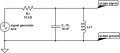
I have tried using using capacitors of different values ( 1u, 100n, 10n, 1n, 100p, 10p ) with large coil. At 1u the signal on oscilloscope is almost flat at 5v. Decreasing the value of capacitor just gives sharper signal of square wave I'm generating with Arduino.
Specifications of small coil:
Resonant frequency = 86kHz (from oscilloscope, see picture below)
Inductance = 36uH ( https://www.omnicalculator.com/physics/resonant-frequency-lc )
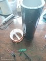
Specifications of large coil:
Diameter coil = 15.35cm (7.675cm radius)
Wire diameter = 0.1601 mm (34 AWG)
Coil height = 39.5cm
Coil resistance = 979 ohms = 3753 feet = 114391.4 cm ( https://cirris.com/wire-resistance-calculator/#quick-calculator )
Calculated result = 2372 turns ( https://www.calctool.org/electromagnetism/helical-coil )
281.2 mH
Problem: Large coil not resonating at resonant frequency. I am trying to verify the calculated result of 281.2mH of large coil with oscilloscope.
What have I tried:
Measure resonant frequency of another small coil successfully. I will attach picture of my small coil resonating with 100n capacitor.
I have tried using using capacitors of different values ( 1u, 100n, 10n, 1n, 100p, 10p ) with large coil. At 1u the signal on oscilloscope is almost flat at 5v. Decreasing the value of capacitor just gives sharper signal of square wave I'm generating with Arduino.
Specifications of small coil:
Resonant frequency = 86kHz (from oscilloscope, see picture below)
Inductance = 36uH ( https://www.omnicalculator.com/physics/resonant-frequency-lc )
Specifications of large coil:
Diameter coil = 15.35cm (7.675cm radius)
Wire diameter = 0.1601 mm (34 AWG)
Coil height = 39.5cm
Coil resistance = 979 ohms = 3753 feet = 114391.4 cm ( https://cirris.com/wire-resistance-calculator/#quick-calculator )
Calculated result = 2372 turns ( https://www.calctool.org/electromagnetism/helical-coil )
281.2 mH
Attachments
-
 213.7 KB Views: 14
 -
 298.4 KB Views: 21
 -
 9.8 KB Views: 19


