measuring da distance!

Thread Starter

Eric007

Joined Aug 5, 2011
1,158
LOL, I forgot to check which pins are set as input and output. Sometimes it's the simplest thing that gets you.
In your init you need to set trisA, B and C to the correct values for the pins you are using. Unused pins should be set to output.
Don't forget to change banks and back.

Oh my God!!! I can't believe this!!! This little thang made me cried...lol

I'm fixing this n check the result!

Regards,
 

Markd77

Joined Sep 7, 2009
2,806
I'm suspecting the getkey routine and button_int isr...
Coz this is da one responsible for the start of the main program...

Also when breadboard is powered with 5V, the unpressed button is read ~5V (a bit less) that means we should wait for a ~0V (button pressed) so main program can start, right? So is that what the current code tells us? I'll have to investigate that!!

What do u think?

Regards,
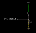
The button is set up as active high, so it needs to be wired like the attached.
 

Attachments

Thread Starter

Eric007

Joined Aug 5, 2011
1,158
So you mean the current code on the getkey routine and the button_int correspond to your attachement? lemme know....

regards,
 

Markd77

Joined Sep 7, 2009
2,806
Just had another look and although the comment says the switch is active high, it actually should be active low, so the resistor and switch should be swapped. Also the comments have the wrong pin.
 

Thread Starter

Eric007

Joined Aug 5, 2011
1,158
so below is how it should be, right? please check portb especially...

banksel TRISC ; bank 1
clrf TRISC ; set PORTC as output
movlw b'10000000' ; setting pin RB4-6 as output
movwf TRISB ; and RB7 as input
bcf TRISA, 2 ; set RA2 as output

i think the whole portc should be output...

please lemme know if the above is correct

regards,
 

Markd77

Joined Sep 7, 2009
2,806
Looks OK, better to clear the whole of portA, because the other pins are unused. Unconnected pins that are set as inputs can cause problems including resets. Best thing is to set them as output and not connect anything to them.
Don't forget to switch back to bank0 at the end.
 

Thread Starter

Eric007

Joined Aug 5, 2011
1,158
there's a lil improvement...

when breadboard = 5V , seven segments display 000!

right now transmitter and receiver circuits have been deconnected from BB, but when button is pressed random value are being displayed...

i have also connected an LED to pin RA2 to see if pulses are being generated from this pin, but the LED does not lit at all so i assume no pulses are coming out from this pin...

attached is the code written into the chip!

regards,
 

Attachments

Markd77

Joined Sep 7, 2009
2,806
The output will be pulsing high for 0.000125 seconds. That is difficult, if not impossible to see, so don't panic about that. If you connect the sensor input pin of the PIC through a 1k resistor to ground, does it show the overrange symbols? If you do the same thing but to 5V with the resistor, does it display a low number, hopefully around 6?

<ed> If you temporarily change the number of pulses from 5 to 250 it might just about be visible at 0.00625 seconds. Use a resistor of around 300 ohms for the LED. It still might be too fast, not really sure. You could also temporarily put a few calls to the 250us delay after bsf pulse.</ed>
 
Last edited:

Thread Starter

Eric007

Joined Aug 5, 2011
1,158
Ohk! You are right! That's impossible to see but I guess we should be able to see something with an oscilloscope...

I initially connected that 1k resistor this way: one side connected to PIC receiver input and the other side to output (ECHO: see schematic) of receiver amplifier...is that how it should be connected??

Coz I didn't really understood ur last post about 1k with ground and 5V

Regards,
 

Markd77

Joined Sep 7, 2009
2,806
It's just to simulate no pulse received: input pin-->resistor--> 0V
or pulse received immediately: input pin-->resistor-->5V
No need to connect the PIC output pin to anything.
 

Thread Starter

Eric007

Joined Aug 5, 2011
1,158
Now I'm thinking which side of the sensor is positive and which are negative?

At the back of each sensor is a black sign on one side and a welding mark (like the one from the soldering iron)...

So which one is what?

Regards,
 

Thread Starter

Eric007

Joined Aug 5, 2011
1,158
Do I still have to connect that 1K resistor between the PIC input pin (receiver) and the receiver amplifier output line?

Regards,
 

Markd77

Joined Sep 7, 2009
2,806
Do I still have to connect that 1K resistor between the PIC input pin (receiver) and the receiver amplifier output line?

Regards,
For the final project, yes, however if you disconnect that and do what I suggested in post #149 and #151 it would be a useful test of the PIC program, before adding the unknown of the receiver amplifier circuit.
 

Markd77

Joined Sep 7, 2009
2,806
Now I'm thinking which side of the sensor is positive and which are negative?

At the back of each sensor is a black sign on one side and a welding mark (like the one from the soldering iron)...

So which one is what?

Regards,
Looking around on the internet, it doesn't matter for this kind of project, the sensor and receiver both work fine connected either way. The only time it makes an difference is when using multiple sensors or transmitters.
 

Thread Starter

Eric007

Joined Aug 5, 2011
1,158
If you connect the sensor input pin of the PIC through a 1k resistor to ground, does it show the overrange symbols? If you do the same thing but to 5V with the resistor, does it display a low number, hopefully around 6?
That's 100% correct!!! I tried the above and I got the --- when connected to ground and exactly 6 when connected to 5V.

But something really strange happening, the sensors are not coonnected, BUT when the whole circuit is connected and breadboard=5V =» when button is pressed, display = --- on first press and the rest of presses.

But when receiver line is disconnected and button is pressed ==»» random values appearing on the display!!

I really don't know how to interpret this...in the above sensors are not connected!!

Regards,
 

Markd77

Joined Sep 7, 2009
2,806
Ok, so maybe something isn't quite right with the receiver circuit or maybe the transmitter circuit. Try putting something hard and flat about 15cm in front of the transmitter and receiver to give it the best chance.
If nothing, try disconnecting the PIC from the receiver circuit, connect an LED and resistor from the receiver circuit output to 0V (ground) and tap the sensor with a screwdriver, see if it flashes.

With the PIC input pin connected to nothing it is normal for it to randomly change the input value as it picks up electrical noise. That is why you get the random values.
 

Thread Starter

Eric007

Joined Aug 5, 2011
1,158
The 15 cm option did not work...

Then I used a 330 ohm resistor...connected it on one side of the LED and the other side of the LED grounded...then the ada side of the resistor was connected to output of the receiver amplifier circuit and nothing still happened....

regards,
 

Markd77

Joined Sep 7, 2009
2,806
I'm not too good at this kind of circuit. Maybe it's a good idea to start a thread just for the circuit in the general electronics chat section to get a few more people to see it and comment. Make sure you mention the op amp substitution.
If you want to post a good photo of the breadboard I can compare it to the schematic to see if there are any errors.
 

Markd77

Joined Sep 7, 2009
2,806
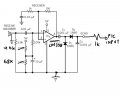
Here's how the input amplifier should be if I understand correctly. I've recommended a couple of resistor changes to move the voltage at their centre point to 1.75V instead of 2.5V. This is because the LM358 isn't rail to rail, but 0-3.5V with a 5V supply.
 

Attachments

Top