Facebook
 Google
 GitHub
 Linkedin

Hi All!
Here's what i'm working on:
Basically, using a PIC16F series, i'm trying to make a utrasonic distance measurer that will output 5 cycles at 40Khz on one I/O then wait for some microseconds then look for the reflection while measuring the time. As soon as the signal is seen, look up the result in a table and display it on 3 digit LED display.
I did some readings on the ressources that you guyz provided some times back and have some ideas about how to solve the problem BUT would need further helps from you guyz!
First, as usual, I would like to discuss the hardware implementation.
And here's how I'm planning to go for it:
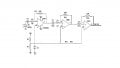
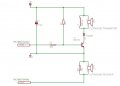
This time around I'm planning to breadboard the circuit with PIC16F877 and use pins RD0-6 for the multiplexing of the 3 seven segments (common cathode), pins RC0, RC1 and RC3 for the transistors (enable), the required pins for ICSP and most importantly the attached schematics for the transmitter and receiver sensors (with pins RA1 and RC2)
Note: this schematic comes from one of your provided ressources, and i think it can be easily breadboarded compared to some crazy schematics I have seen.
Ok, i don't wana make this too long so I stop here for the hardware part and will talk about the software one in my next post while having your comments on the hardware!
Your comments will be greatly appreciated
Kindly regards, Eric
Here's what i'm working on:
Basically, using a PIC16F series, i'm trying to make a utrasonic distance measurer that will output 5 cycles at 40Khz on one I/O then wait for some microseconds then look for the reflection while measuring the time. As soon as the signal is seen, look up the result in a table and display it on 3 digit LED display.
I did some readings on the ressources that you guyz provided some times back and have some ideas about how to solve the problem BUT would need further helps from you guyz!
First, as usual, I would like to discuss the hardware implementation.
And here's how I'm planning to go for it:
This time around I'm planning to breadboard the circuit with PIC16F877 and use pins RD0-6 for the multiplexing of the 3 seven segments (common cathode), pins RC0, RC1 and RC3 for the transistors (enable), the required pins for ICSP and most importantly the attached schematics for the transmitter and receiver sensors (with pins RA1 and RC2)
Note: this schematic comes from one of your provided ressources, and i think it can be easily breadboarded compared to some crazy schematics I have seen.
Ok, i don't wana make this too long so I stop here for the hardware part and will talk about the software one in my next post while having your comments on the hardware!
Your comments will be greatly appreciated
Kindly regards, Eric
Attachments
-
 33.2 KB Views: 51