Facebook
 Google
 GitHub
 Linkedin
HI.
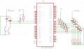
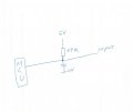
My MCU 16F18877
is attached as the schematic.
MCU detect the input as LOW when it should be HIGH,
When the end wire is floating,
When i connect the end to 0V it do not detect anything, but if held to +5V it detect as high,
Why ? is my resistor to big or ?
My MCU 16F18877
is attached as the schematic.
MCU detect the input as LOW when it should be HIGH,
When the end wire is floating,
When i connect the end to 0V it do not detect anything, but if held to +5V it detect as high,
Why ? is my resistor to big or ?
Attachments
-
 39.5 KB Views: 21