 Facebook
 Google
 GitHub
 Linkedin
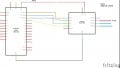
MAX31865
- Thread starter jvdrc123
- Start date


| Thread starter | Similar threads | Forum | Replies | Date |
|---|---|---|---|---|
| E | MAX31865 measurement step | Sensor Design & Implementation | 1 | |
| D | Looking for similar IC to MAX31865 or other solutions | Homework Help | 0 | |
| G | looking for alternative part of MAX31865 IC RTD | Datasheets, Manuals & Parts Identification | 2 |


